|
|
- Background
- Magnetic field lines
- Magnetic Field Lines for Current in Coil of Wire (Fig.
1a)
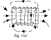
- Curl the fingers of your right hand in the direction
of the current. Your thumb points in the direction
of the field along the axis of the coil.
- The field at other points is tangent to the field
lines which are dashed in Fig. 1a.
- Magnetic Field Lines for Bar Magnet (Fig. 1b)
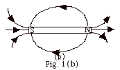
- Magnetic field lines leave North pole and go to
South pole. The field at any point is tangent to the
field line.
- North pole of magnet acts like current carrying
coil of wire with current in counterclockwise direction
as you view that end of the coil.
- Before we knew the cause of magnetism was a net
flow of charge, we said a circular coil with current
in counterclockwise direction as you view that end
of the coil acted like a North pole.
- By experiment we find that a North Pole repels another
North pole or a coil with the current in a counterclockwise
direction.
- Magnetic Flux

- FB =
B . A = BA cos
 B,A
for B constant. B,A
for B constant.
- For Fig. 2a,
 B,A
= 90o. cos 90o = 0 and
FB = 0. B,A
= 90o. cos 90o = 0 and
FB = 0.
- For Fig. 2b, FB
= BA cos
 B,A. B,A.
- For Fig. 2c,
 B,A
= 0o. cos 0o = 1 and
FB = BA. B,A
= 0o. cos 0o = 1 and
FB = BA.
- For Fig. 2d, notice that

- If B, A, or
 B,A
vary, FB
= ∫ B . dA. B,A
vary, FB
= ∫ B . dA.
- The Experiment
- First we calibrate a galvanometer to detect the presence
and the direction of a current. In Fig. 3 when current
enters the terminal on the right hand side of the galvanometer,
the needle deflects to the left.

- In Fig. 4a, the bar magnet is at rest. There is no current
in coil of wire and the galvanometer does not deflect.

- In Fig. 4b, the magnet moves toward the coil and the
galvanometer deflects toward the left indicating an induced
current and associated induced magnetic field (shown by
dashed line) opposing the field of the magnet.

- In Fig. 4c, the rate of change of the magnetic flux
produced by the magnet has increased and there is a greater
current in the galvanometer.

- In Fig. 4d, the magnet is inside the coil at rest. Current
is zero.

- In Fig. 4e, the magnet moves to the right. Current
reverses.

- Results of the Experiment
The induced current creates an induced magnetic field that
opposes the change produced by the external magnetic field.
In this experiment the bar magnet provided the external field.
- When the magnet was at rest there was no induced current
(Fig. 4a above).
- When the North pole of the magnet with its field toward
the left moved toward the right face of the coil, the
induced current in the coil was counterclockwise as viewed
from its right end with the Coil's induced field to the
right. Another way of looking at this is the right end
of the coil acts like a North pole and repels the North
pole of the magnet as you move the magnet toward it. You
must exert a force through a distance doing work to induce
a current in the coil (Fig. 4b above).
- The greater rate of change of magnetic flux, the greater
induced current. As the magnet gets nearer to the coil,
the flux changes more rapidly. You can also see this by
bringing up two magnets at the same speed of one or bringing
up one more rapidly (Fig. 4c above).
- When the magnet is at rest, there is no change in magnetic
flux and no induced current (Fig. 4d above).
- When the North pole is moved away from the right end
of the coil the current in the coil reverses. The end
of the coil nearest the magnet acts like a South pole
and you must do work to remove the North pole of the magnet
and induce a current in the coil (Fig. 4e above).
- Sample problems in 106
Problem Set for Induction: 1, 2.
- Faraday's Law
- Induced emf = the rate of change of magnetic flux.
- Since FB
= ∫ B . dA, you can change
the magnetic flux by changing the magnetic field, the
area through which the field exists or the angle between
the magnetic field and the area.
- Lenz's Law states that the direction of the induced
current is such to oppose the change that produced it.
Lenz's Law is really a statement of conservation of energy.
In order to get an induced emf or current, you must do
work.
- Motional emf
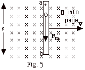
- As conductor in Fig. 5 moves to the right, the electrons
in the conductor move with it velocity v and experience
a magnetic force down equal to qvB, where q is the charge
of the electron. They accumulate at the bottom of the
conductor leaving the top of the conductor with an excess
of positive charge.
- This separation of charge produces an electric field
from a to b that results in an electric force up on the
electron equal to qE, where q is the charge of the electron.
- When the electric force equals the magnetic force, qE
= qvB, the motion of the electron ceases and the
electric field in the conductor E = vB. The potential
difference between the ends of the conductor

- The motional
 . In
Fig. 5, B was perpendicular to v. . In
Fig. 5, B was perpendicular to v.
If the magnetic field is not perpendicular to the velocity,
the motional 
- Alternating Current Generator
- In Fig. 2b above, the magnetic flux FB
= BA cos
 B,A. B,A.
- Let
 B,A
= Q = wt,
where w equals
the angular velocity of the rotating coil. Then
FB = BA
cos wt and
e = - NdFB/dt
= N wBA sin wt, B,A
= Q = wt,
where w equals
the angular velocity of the rotating coil. Then
FB = BA
cos wt and
e = - NdFB/dt
= N wBA sin wt,
where N = the number of turns of the coil.
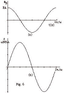
- Figure 6a and 6b below are plots of the magnetic flux
and the electromotive force as a function of time t, respectively.
- Sample problems in 106
Problem Set for Induction: 3-14.
- The Production of an Electric Field by a Changing Magnetic Flux
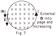
- To describe what happens in Fig. 7, we can say the motion
of charge in the wire is produced by an induced current due
to the change in magnetic flux through the loop. We can also
explain it as the production of an electric field that produces
a motion of charge.
- To put this statement into a mathematical form, we recall
that electromotive force e
equals the energy per unit charge or work done per unit charge
and the electric field equals the force per unit charge. The
work done per unit charge around the loop of distance 2pr
equals E(2pr), or
e = E(2pr)
= -dFB /dt.
(Equation
1)
- Inductance L
- e = - dF/dt
= L dI/dt.
The unit of inductance is the Henry (H) = 1 volt/(A/s).
- Inductance is the third circuit element.
By comparison, resistance R = Vab/I and capacitance
C = q/Vab.
- Energy associated with inductor U = 1/2 LI2.
- Maxwell's Suggestion
- Since Nature is amazing symmetrical, Maxwell predicted that
a changing electric flux should produce a magnetic field.
The actual equation is similar to Eq.1 above, but it is only
dimensionally correct if
B(2pr) = µ0e0
dFE /dt (Equation
2)
- While it is above the level of Physics 106, we can tell
you that these changing electric and magnetic fields are propagated
as a wave. The use of Maxwell's Equations (there are really
four) can be put together to get a wave velocity which must
equal (1/µ0e0)1/2 in
a vacuum or in air. Let's try it:
µ0 = 4px
10-7 N/A2
1/µ0 = 1/(4px
10-7 N/A2
1/e0 = 4pk
= 4p(9 x 10⁹ N-m2/C2)
(1/µ0e0)
= (1/(4px10-7
N/A2)(4px
9 x 109 N-m2/C2)
= 9 x 10¹⁶
(A/C)2m2
= 9 x 10¹⁶
(m/s)2 (1/µ0e0)1/2
= 3 x 10⁸
m/s
= the speed of light
in a vacuum.
- As the late Professor Feynman of Cal Tech suggested, Genesis
should be changed to read, "Let there be electricity
and magnetism and there will be light."
|
|