|
|
|
1.
|
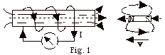
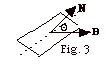
The left side of the magnet is a north-seeking pole and the
right side is a south-seeking pole. As the bar magnet advances
toward the coil of wire, its magnetic field lines to the left
are thrust into the coil. To oppose the change that produced
it, the magnetic field lines of the induced current must be
to the right. If you curl the fingers of your right hand in
the direction of the current, your thumb points in the direction
of the magnetic field lines produced in the coil as shown in
Fig. 1 above.
|
|
|
2.
|

As the magnet moves toward the coil, it induces a current in
the coil in the direction shown in Fig. for #2 above. The opposing
magnetic field of the induced current slows down the magnet.
The magnet experiences an acceleration down due to the gravitational
force and and an acceleration up due to the magnetic force of
the induced field. Since the rate of change of the magnetic
flux due to the magnet varies with time, the magnetic force
will vary and the acceleration is not constant.
|
|
|
3.
|
FB = B .
A = BA cos 0o = BA
e = - DFB/Dt
= - (DB/Dt)A
= - [(0.040 -0.080)N/A-m/(2.0 s)]4.0 m2
= - 0.080 N-m/C = - 0.080 V
I = e/R = 0.080 V/0.04 W
= 2 A
With the magnetic field into the page and decreasing, the sense
of the current will be such to oppose the change that produced
it or clockwise. A clockwise-induced current produces a magnetic
field into the page and opposes the decreasing external magnetic
field.
|
|
|
4.
|
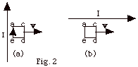
The current in the very long wire produces a magnetic field
into the loop of wire acde
in Fig. 2 above. This field decreases with distance from the
wire. As the coil in Fig. 2a moves away from the current-carrying
wire, the magnetic field due to the wire through the coil decreases.
To oppose this change, the induced current in the loop acde
is clockwise. A clockwise current will produce a field into
the page. When the loop in Fig. 2b moves parallel to the current
I of the long wire, there is no change in the magnetic field
through the loop acde
and there is no induced current in it.
|
|
|
5.
|
- The length of the chain = 0.40p
m = 2pr and r = 0.20
m.
A = pr2 =
p(0.040 m2).
Ignoring the minus sign,
e = DF/Dt
= D(BA)/Dt
= [(0.060 - 0.010)N/A-m](0.040p
m2)/0.50 s
= 0.004p
V.
I = e /R = 0.004p
V/0.001 W = 4p
A.
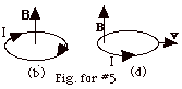
- The sense of the current is shown in Fig. for #5b above.
Notice the induced currrent produces a magnetic field that
opposes DB.
- The chain contracts "trying" to keep the increasing
flux out of the loop.
- e = DF/Dt
= D(BA)/Dt
= [(0 - 0.060)N/A-m](0.040pm2)/0.30
s = - 0.008p V.
I = e /R = 0.008p
V/0.001 W = 8p
A.
The diagram is shown in Fig. for #5d above. At the left
end of the loop, the current I is out of the page, the magnetic
field B is up, and the force on the loop is to the left.
The magnetic force hinders the withdrawal of the chain from
the field.
|
|
|
6.
|
- F = BA cos Q
= BA cos wt. The magnetic
flux equals the component of the magnetic field perpendicular
to the area times the area.
- e = - dF/dt
= + wBA sin wt
= wBA sin Q.
- The magnetic flux is a maximum when Q
is 0o or ± (180o). This occurs
when the plane of the coil is perpendicular to the magnetic
field.
- The emf is a maximum when Q
is p/2 (90o)
or 3p/2 (270o).
This occurs when the plane of the coil is parallel to the
magnetic field and the magnetic flux is changing most rapidly.
|
|
|
7.
|
- The initial magnetic flux (FB)i
= B(area) = B(xL).
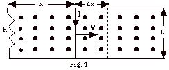
- The later magnetic flux = B(x + Dx)L.
The change in flux = DF=
BL{(x + Dx) -x} = BLDx.
- The electromotive force = e =
DF/Dt
= BL(Dx/Dt)
= BLv.
- I haven't used the minus sign because we find the sense
of the current from Lenz's law. The sense of the induced
current is such to oppose the change that produces it. As
the rod moves to the right, the magnetic flux out of the
page increases. To oppose this, the induced current must
be clockwise. A current clockwise will produce a field into
the page. If you curl the fingers of your right hand clockwise,
your thumb points into the page.
- The current I = e/R
= BLv/R.
- Power dissipated in the resistance R = I2R
= (BLv/R)2R = B2L2v2/R,
since I = e/R = BLv/R.
- In Fig. 4 above, the induced current is clockwise, which
means positive charge moves down through the bar of length
L. The force on the current carrying bar due to the magnetic
field B is Fm = I( L x B).
L is taken in the direction of the current or down.
B is out of the page, so Fm can
be neither in or out nor up or down. It must be to the right
or the left. If you rotate vector L into vector B,
you find Fm is to the left. The external
agent must exert a force F equal in magnitude to Fm
to move the rod with a constant velocity. F
= Fm = ILB sin 90o = ILB = (BLv/R)LB
= B2L2v/R.
- Power = work/time = (force x distance)/time = force x
(distance/time) = force x v. Power generated by external
agent = (B2L2v/R)v = B2L2v2/R.
- Notice that the answers to (f) and (h) are the same, as,
of course, they should be if you believe in conservation
of energy and all those good things. The external agent
must do work in order to produce the induced emf and current.
Lenz's law is just a statement of conservation of energy.
|
|
|
8.
|
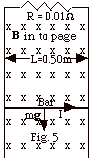
- As the bar slides down, the magnetic flux into the page
increases. To oppose this, the induced current must be to
the right in the bar. The induced current then produces
a magnetic field out of the page inside the loop.
- The "motional emf" = BLv. I = e/R
= BLv/R. The magnetic force on the bar of length L
is Fm = (I)LB sin 90o = (BLv/R)LB(1)
= B2L2v/R. For a current to the right
in a field into the page the force on the bar is up. For
constant velocity, Fnet = B2L2v/R
- mg = 0 and v = mgR/B2L2
= 0.50 kg(9.8 m/s2)(0.01 N-m/A-C)/(0.20
N/A-m)2(0.5 m)2 = 4.90 m/s.
|
|
|
9.
|
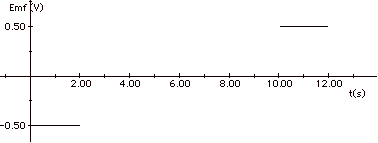
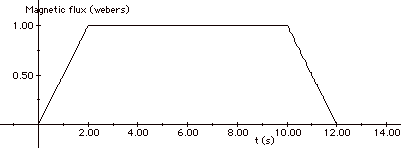
After 1 s, one-half of the loop is in the magnetic field so
the magnetic flux = BA = (1T)(0.5m2) = 0.5 Wb.
After 2 s, the entire loop is in B: FB
= 1 Wb.
From t = 2s to t = 10 s, the entire
loop is in the field.
At t =10 s, the front edge of the loop reaches the edge
of the field boundary.
At t = 11 s, only half the loop is in the field, and at
t = 12 s none of the loop is in the field.
From t = 12 s on the flux is zero.
Since the emf = - dFB/dt,
you find the emf from the negative slope of the
FB vs t
graph, as shown in the figures above. As the loop enters
the magnetic field, the sense of the induced current is clockwise
in the loop producing a magnetic field into the page to oppose
the change that produced it. As it leaves the field, the
current is counterclockwise.
From t = 0 to t = 2 s, and from t =
10 s to t = 12 s,
I = e/R = 0.50 V/0.01W
= 50 A.
From t = 2s to t = 10 s, I = 0.
|
|
|
10.
|
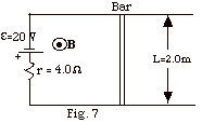
For the bar to experience no net force, the net emf in the circuit,
e = 20 V of the battery,
is balanced by an opposing emf due to the change in magnetic
flux in the loop of Fig. 7 above.
20 V = 20 J/C = 20 N-m/C = DF/Dt
= D(BA)/Dt
= [(1.10 - 0.10)N-s/C-m][(2.0
m)(x)]/0.10 s
x = 1.0 m
|
|
|
11.
|
To oppose the change which produced it,
as the magnetic field increases out of the page, the bar must
move to the right to increase the area through which the field
passes so the "back" emf will increase to 20 V.
20 V = 20 J/C = 20 N-m/C = DF/Dt
= D(BA)/Dt
= D(BLx)/Dt
= BLv
= [1.10 N-s/C-m][(2.0
m)(v)]
v = 9.1 m/s
|
|
|
12.
|
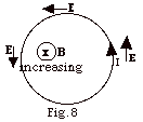
We can, and do, think of a changing magnetic flux producing
an electric field. In Fig. 8 above the electric field line is
counterclockwise. At any point the electric field is tangent
to the circle. This electric field produces a counterclockwise
current in the wire opposing the change in the magnetic field.
Even if the wire is not there, the electric field with field
lines counterclockwise is produced by a magnetic field into
the page and increasing.
|
|
|
13.
|
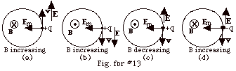
For a particle to move in a circle, there must be a force in
to the center of the circle to produce the centripetal acceleration.
- In Fig. for #13a, with the magnetic field B into
the page, the magnetic force Fm will be
in to the center of the circle when the charged particle
travels counter-clockwise.
If the magnetic field into
the page is increasing,
the induced electric field E will always be in the
same
direction as the velocity of the particle and its velocity
will increase.
- In Fig. for #13b, with the magnetic field B out
of the page, the magnetic force will be in to the center
of the circle when the charged particle travels clockwise.
If the magnetic field out
of the page is increasing,
the induced electric field E will always be in the
same
direction as the velocity of the particle and its velocity
will increase.
- In Fig. for #13c, with the magnetic field B out
of the page, the magnetic force will be in to the center
of the circle when the charged particle travels clockwise.
If the magnetic field out
of the page is decreasing,
the induced electric field E will always be opposite
to the direction of the velocity of the particle and its
velocity will decrease.
- In Fig. for #13d, with the magnetic field B into
the page, the magnetic force will be in to the center of
the circle when the negatively charged particle travels
clockwise.
If the magnetic field into
the page is increasing,
the induced electric field E will always be in the
opposite
direction to the velocity of the electron and its velocity
will increase.
Remember the direction of the electric
field is the direction in which a positive charge is urged.
An electric field up exerts a force down on an electron.
|
|
|
14.
|
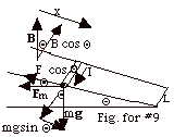
dFB = B
. dA = B xL cos Q
e = - dFB/dt
= - B (dx/dt)L cos Q
= - BvL cos Q
I =e/R = BvLcos Q/R
Fm = I(L x B)
Fm = ILB sin 90o = ILB = [BvL cos
Q/R](LB) = (BL)2v
cos Q/R
The direction of the magnetic force is to the left. The component
of the magnetic force up the plane equals
Fm cos Q
= [(BL)2v cos Q/R]cos
Q= (BL)2 v
cos2 Q/R.
The component of the gravitational force down the plane = mg
sin Q.
For a constant velocity, Fnet = mg sin Q
- (BL)2 v cos2 Q/R
= 0 or
v = mgR sin Q/(BL cos Q)2.
|
|
|