|
|
- Background
- Magnetic field lines
- Magnetic Field Lines for Current in Coil of Wire (Fig.
1a)
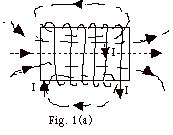
- Curl the fingers of your right hand in the direction
of the current. Your thumb points in the direction
of the field along the axis of the coil.
- The field at other points is tangent to the field
lines which are dashed in Fig. 1a.
- Magnetic Field Lines for Bar Magnet (Fig. 1b)
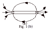
- Magnetic field lines leave North pole and go to
South pole. The field at any point is tangent to the
field line.
- North pole of magnet acts like current carrying
coil of wire with current in counterclockwise direction
as you view that end of the coil.
- Before we knew the cause of magnetism was a net
flow of charge, we said a circular coil with current
in counterclockwise direction as you view that end
of the coil acted like a North pole.
- By experiment we find that a North Pole repels another
North pole or a coil with the current in a counterclockwise
direction.
- Magnetic Flux

- FB =
B . A = BA cos
 B,A
for B constant. B,A
for B constant.
- For Fig. 2a,
 B,A
= 90o. cos 90o = 0 and
FB = 0. B,A
= 90o. cos 90o = 0 and
FB = 0.
- For Fig. 2b, FB
= BA cos
 B,A. B,A.
- For Fig. 2c,
 B,A
= 0o. cos 0o = 1 and
FB = BA. B,A
= 0o. cos 0o = 1 and
FB = BA.
- For Fig. 2d, notice that

- If B, A, or
 B,A
vary, FB
= ∫ B . dA. B,A
vary, FB
= ∫ B . dA.
- The Experiment
- First we calibrate a galvanometer to detect the presence
and the direction of a current. In Fig. 3 when current
enters the terminal on the right hand side of the galvanometer,
the needle deflects to the left.

- In Fig. 4a, the bar magnet is at rest. There is no current
in coil of wire and the galvanometer does not deflect.

- In Fig. 4b, the magnet moves toward the coil and the
galvanometer deflects toward the left indicating an induced
current and associated induced magnetic field (shown by
dashed line) opposing the field of the magnet.

- In Fig. 4c, the rate of change of the magnetic flux
produced by the magnet has increased and there is a greater
current in the galvanometer.

- In Fig. 4d, the magnet is inside the coil at rest. Current
is zero.

- In Fig. 4e, the magnet moves to the right. Current
in coil reverses.

- Results of the Experiment
The induced current creates an induced magnetic field that
opposes the change produced by the external magnetic field.
In this experiment the bar magnet provided the external field.
- When the magnet is at rest there is no change of flux
or induced current (Fig. 4a above).
- When the North pole of the magnet moved toward the right
face of the coil, the induced current in the coil was
counterclockwise as viewed from its right end of the coil.
Another way of looking at this is the right end of the
coil acts like a North pole and repels the North pole
of the magnet as you move the magnet toward it. You must
exert a force through a distance doing work to induce
a current in the coil (Fig. 4b above).
- The greater rate of change of magnetic flux, the greater
induced current. As the magnet gets nearer to the coil,
the flux changes more rapidly. You can also see this by
bringing up two magnets at the same speed of one or bringing
up one more rapidly (Fig. 4c above).
- When the magnet is at rest, there is no change of flux
and no current (Fig. 4d above).
- When the North pole is moved away from the right end
of the coil the current in the coil reverses. The end
of the coil nearest the magnet acts like a South pole
and you must do work to remove the North pole of the magnet
and induce a current in the coil (Fig. 4e above).
- Faraday's Law
- Induced emf = the rate of change of magnetic flux.
- Since FB
= ∫ B . dA, you can change
the magnetic flux by changing the magnetic field, the
area through which the field exists or the angle between
the magnetic field and the area.
- The direction of the induced current is given by Lenz's
Law: The direction of the induced current is such to oppose
the change that produced it. Lenz's Law is really a statement
of conservation of energy. In order to get an induced
emf or current, you must do work.
- Motional emf
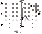
- As conductor in Fig. 5 moves to the right, the electrons
in the conductor move with its velocity v and experience
a magnetic force down equal to qvB, where q is the charge
of the electron. They accumulate at the bottom of the
conductor leaving the top of the conductor with an excess
of positive charge.
- This separation of charge produces an electric field
from a to b that results in an electric force up on the
electron equal to qE, where q is the charge of the electron.
- When the electric force equals the magnetic force, qE
= qvB, the motion of the electron ceases and the
electric field in the conductor E = vB. The
potential difference between the ends of the conductor
Vab = E =
(Bv) =
(Bv)
- The motional emf = Bv
 . In
Fig. 5, B was perpendicular to v. . In
Fig. 5, B was perpendicular to v.
If the magnetic field is not perpendicular to the velocity,
the motional emf = Bv sin sin  B,v. B,v.
- Alternating Current Generator
- In Fig. 2b above, the magnetic flux FB
= BA cos
 B,A. B,A.
- Let
 B,A
= Q = wt,
where w equals
the angular velocity of the rotating coil. Then
FB = BA
cos wt and
e
= - NdFB/dt B,A
= Q = wt,
where w equals
the angular velocity of the rotating coil. Then
FB = BA
cos wt and
e
= - NdFB/dt
= N wBA sin wt,
where N = the number of turns of the coil.
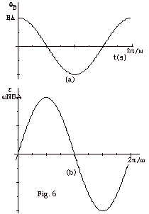
- Figure 6a and 6b below are plots of the magnetic flux
and the electromotive force as a function of time t, respectively.
- Sample problems in 108
Problem Set for Induction: 1-10.
- The Production of an Electric Field by a Changing Magnetic Flux
- The electromotive force e
equals the energy per unit charge and the electric field E
equals the force per unit charge.
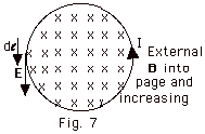
In Fig. 7 above we can explain the motion of charge in the
wire as an induced current. We can also explain it as the
production of an electric field that, in turn, produces a
motion of positive charge as a current. The work done per
unit charge around the loop of length 2pr
equals e = E(2pr) = - dFB /dt.
- In general we may write
 E
• d E
• d =
=  B
• dA B
• dA
- Sample problem in 108
Problem Set for Induction: 12
- Self-inductance L = NFB/I
- Calculation of L for a solenoid
For a solenoid, B = µonI = µo(N/ )I, )I,
where n = the number of turns per unit length = N/ . .
NFB = µo(N2/ )Ipr2,
where r is the radius of the solenoid. )Ipr2,
where r is the radius of the solenoid.
L = NFB /I
= µo(N2/ )(pr2). )(pr2).
- Energy in Magnetic Field
- Since L = NFB/I,
L = N (dFB/dt)/(dI/dt)
= e/(dI/dt).
- Energy = dU = (power)dt = eI
dt = L(dI/dt)I dt = LI dI.
U = Lo ∫I I dI = 1/2 LI2.
- Using L from solenoid, the magnetic energy
UB = 1/2 [(µo(N2/ )(pr2)]I2 )(pr2)]I2
= 1/2[µo(N2/ )(pr2)][B/µo(N/ )(pr2)][B/µo(N/ )]2 )]2
= (1/2µ0)
B2[ pr2] pr2]
= (1/2µo)
B2[volume]
- While we have derived this from L for a solenoid, in
general
UB = 1/2 (B2/µo)A(length)
and the magnetic energy density
uB = (1/2µo )B2.
Compare with electric energy density
uE = (1/2) eo
E2.
- Example
Find the magnetic energy stored for a < r < b for
the coaxial inductor shown in Fig. 8 below.
Assume that the inductor is sufficiently long ( >> b),
or that the gap is sufficiently small, that end effects
can be neglected. >> b),
or that the gap is sufficiently small, that end effects
can be neglected.

From Ampere's law, we know that for a < r <
b, B = µoI/2pr.
The volume element is the volume of a cylindrical
shell with radius r, surface area 2pr ,
and thickness dr. ,
and thickness dr.
dV = 2pr dr
dr
U = (1/2µo) a∫b
B2 dV
= (1/2µo) a∫b
[µoI/2pr]
2 2pr dr
dr
= [µoI2 /4p]
ln (b/a) /4p]
ln (b/a)
- Sample problems in 108
Problem Set for Induction: 11, 15.
- R-L Circuits
- Inductance L = DVL/(dI/dt),
where DVL is
the potential difference across the inductor and dI/dt is
the rate of change of current in the inductor.
- Unit of Inductance = 1 Henry (H) = 1V-s/A
- Similar to resistance and capacitance, the inductance
depends only on the geometry of the conductor.
- Build up of current
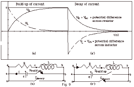
- When a source of emf is connected across a resistor
and inductor wired in series with a battery (Fig. 9b above),
the current goes from zero to some finite value in a very
short time. Since the rate of change of current is very
high, the potential difference across the inductor = Vcb=
L(dI/dt) is very high, while the small current makes the
potential difference across the resistor Vac
= IR very small. As time passes, the current builds up
and the rate of change of current decreases. After a very
long time, it is as though the inductor were not in the
circuit and the total emf is across the resistor giving
a maximum current = e/R.
A plot of Vac and Vcb
(with dashes) for the build up of the current is shown
in Fig. 9a above.
- For the build up of the current,
I(t) = (e/R)(1
- e-Rt/L)
Vac(t) = IR = e(1
- e-Rt/L)
Vcb(t) = L dI/dt = L(- e/R)
e-Rt/L (-R/L) = e
e-Rt/L
- Decay of the Current
- When the battery is removed and a wire is placed across
the resistor and the inductor (Fig. 9b above), the potential
difference Vab = 0. As the current decreases, the inductor's
"back emf" opposes the decrease in current.
A plot of Vac and Vbc (with dashes) for the decay of the
current is shown in Fig. 9a’ above.
- For the decay of the current,
I(t) = (e/R)e-Rt/L
Vac(t) = IR = e
e-Rt/L
Vcb(t) = L dI/dt = L(e/R)(e-Rt/L)(-R/L)
= -ee-Rt/L
- Sample problem in 108
Problem Set for Induction: 13
- L-C Circuits
- Comparison of LC-oscillator with spring

| |
Spring |
|
Oscillator |
| |
Fnet =
ma |
|
Vab = Vac
+ Vcb |
| |
- kx =
m dv/dt |
|
0
= q/C + L dI/dt |
| Since
v = dx/dt, |
Since
I = dq/dt, |
| |
dv/dt = d/dt(dx/dt)
= d2x/dt2 |
|
dI/dt = d/dt(dq/dt)
= d2q/dt2 |
| |
-kx = m d2x/dt2
or |
|
-q/C = L d2q/dt2
or |
| |
d2x/dt2
+ (k/m)x = 0 |
|
d2q/dt2
+ (1/LC)q = 0 |
| |
w
= 2pf = (k/m)1/2 |
|
w
= 2pf = (1/LC)1/2 |
- Charge, Current, and Potential
Energy as a function of time for L-C circuit
- For fully charged capacitor
at time t = 0,
q(t) = Q0 cos wt,
with w = 2pf
= (1/LC)1/2.
- I(t) = dq/dt = I(t) = wQ0
sin wt
- Electric potential energy
Ue = 1/2 q2/C = (1/2C) Q02
cos2 wt
- Magnetic potential energy
Um = 1/2 LI2 = (L/2) w2Q02
sin2 wt
- Since w=
2p/T,
maximum electric
energy occurs at t = 0, T/2, 2T . . . maximum
magnetic energy occurs at t = T/4, 3T/4 . . .
Sample problem in 108
Problem Set for Induction: 14
- Electromagnetic Waves
- From Faraday's law we find
 (Equation
1)
This equation states that a changing magnetic flux produces
an electric field.
- From Ampere's law
 (Equation
2)
This equation states that a current produces a magnetic field.
- Maxwell's addition
- Since nature is amazingly
symmetrical, Maxwell believed that a changing electric
flux should produce a magnetic field.
- As an example, he pointed
out the discontinuity in the magnetic field while a capacitor
is charged. In Fig. 11 below, you see the magnetic field
lines associated with the current entering the capacitor
and leaving the capacitor, but there is apparently no
magnetic field inside the capacitor.

- While the capacitor is charging,
the electric field inside the capacitor is changing since
E = q/eoA.
dE/dt = (dq/dt)/eoA
or
(dq/dt) = current = (eoA)
dE/dt.
Maxwell called this current a displacement current
Id and generalized it by writing Id
= eo d/dt
∫ E . dA (Equation
3)
- With this addition we rewrite
Eq. 2
 (Equation
4)
Eq. 4 states that a changing
electric flux produces a magnetic field even in the absence
of a current.
- Maxwell suggested that a
changing electric field produced a magnetic field, which
if changing, produced an electric field, which if changing,
produced a magnetic field, etc. He hypothesized that these
disturbances would be transmitted as an electromagnetic
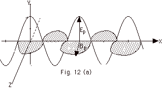
wave. Figure 12a below is a representation of an electromagnetic
wave traveling in the X-direction with the electric vector
in the X-Y plane and the magnetic vector in the Y-Z plane.
- The equations of motion for
the E and B vectors are
E = Ep cos
(kx - wt) (Equation 5)
B = Bp cos (kx - wt)
(Equation
6)
where k = 2p/l
and w = 2pf.
Since lf = c, w/k
= (2pf)/(2p/l)
= lf = c.
- Evaluating paths in Fig. 12b
and 12c.
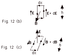
Let us evaluate Eq.1 for the path in Fig. 12b above.
You choose the direction of going around the loop by pointing
the thumb of your right hand in the direction of B.
Your fingers then curl clockwise in the direction of the
path. For this path, the  E,
ds along the right-hand side of the loop is 0o
and along the left-hand side of the loop it is 180o. E,
ds along the right-hand side of the loop is 0o
and along the left-hand side of the loop it is 180o.

E •
ds = (E + dE) ds on the right side of
length h and –E ds for the left side. For the sides
of length dx,  E,
ds is 90o and cos 90o = 0.
There is no contribution for these lengths. E,
ds is 90o and cos 90o = 0.
There is no contribution for these lengths.
Letting B = the average value of the loop of area h dx,
-d/dt ∫ B . dA = -dB/dt
hdx.
Thus  becomes becomes
(E + dE)h – Eh = - dB/dt h dx or
dE/dx = - dB/dt,
or in terms of partial derivatives,
∂E / ∂x = - ∂B / ∂t
(Equation
7)
- Write Maxwell's equation in
free space, that is, assume there is
no "real" current I.
- Then
 (Equation
4) (Equation
4)
becomes  (Equation
4’) (Equation
4’)
- Evaluate Eq. 4’
for the path of Fig. 12c above.
You choose the direction of going around the loop
by pointing the thumb of your right hand in the direction
of E. Your fingers then curl in the direction
of the path. For this path, the  B,
ds along the left-hand side of the loop is 0o
and along the right-hand side of the loop it is 180o. B,
ds along the left-hand side of the loop is 0o
and along the right-hand side of the loop it is 180o.
B . ds = - (B + dB)dx
on the right side of length h and B dx for the left
side. For the sides of length dx, the  B,
ds = 90o and there is no contribution
to those sides. B,
ds = 90o and there is no contribution
to those sides.
 =-dB dx
Letting E = the average value of the loop of area
h dx,
µoeo
d/dt ∫ E . dA = µoeo
dE/dt hdx or
Eq. 4' becomes
- dB/dx
= µoeo
dE/dt
or in terms of partial derivatives
- ∂B / ∂x = µoeo
∂E / ∂t (Equation
8)
Taking the partial derivative
of Eq. 7 with respect to x gives
∂2E / ∂x = -
( ∂ / ∂x)∂B / ∂t
(Equation
9)
Taking the paratial derivative
of Eq. 8 with respect to t gives
- (∂ / ∂t)∂B / ∂x
= µoeo
(∂2E / ∂t2) (Equation
10)
Since the order of differentiation
does not make any difference, you can equate the left
side of Eq. 9 to the right side of Eq. 10:
∂2E / ∂x2 =
µoeo
(∂2E / ∂t2)
(Equation
11)
Compare Eq. 11 with wave
equation of wave along rope
∂2y / ∂x2 =
(1 / v2) (∂2y / ∂t2)
The equations are identical
for a wave traveling with a velocity (1/µoeo)1/2
and changing electric field E, and a wave with a velocity
v with changing displacement of the rope y from the
equilibrium position, if c = (1/µoeo)1/2.
- Since µo=
4p x 10-7
N/A2 and
eo
= 8.85 x 10⁻¹² C2/N-m2,
(1/µoeo)1/2
= 1/[(4p x 10-7
N/A2)( 8.85 x 10⁻¹² C2/N-m2)]1/2
=
3.00 x 10⁸ m/s!
As the late Richard Feynman said in a rewrite of Genesis,
"Let there be electricity and magnetism and there
will be light."
c = (1/µoeo)1/2
- If you take the derivative
of Eq. 5 with respect to x and the derivative of Eq. 6
with respect to t and substitute into Eq. 7, you find
- kEp
sin(kx - wt) = - wBp
sin(kx - wt) or
Ep = (w/k)Bp
= {2pf/(2p/l)Bp
or
Ep = Bp(fl)
Bp = Ep/c
- The Poynting vector S
- S = 1/µo
E x B.
- S is the energy/second per
m2. Since
energy/second = power = P,
S = power/area.
- Frequently you can solve
problems by checking units.
The unit of power is J/s = W.
The unit of S is W/m2.
- The direction of S is
given by E x B.
In Fig. 12, E = Ej and
B = Bk.
Since j x k = i, and S =
1/µo E x B, S
is in the positive X-direction.
- Magnitude of S = EB/µo
= E2/cµo.
- Average value of Sav
= (E2)av/cµo = (Ep)2[cos2(kx
- wt)]av/cµo.
[cos2(kx - wt)]av
= 1/2 and Sav = (Ep)2/2cµo.
- Power (W) = Energy/time (J/s).
- Average value of S = Intensity
(W/m2) = Power (W)/Area (m2).
- Sample problems in 108
Problem Set for Induction: 16-20.
- Momentum and Pressure of an Electromagnetic
Wave
- Assume that an initially at rest,
positive charge q is in the path of a wave (Fig. 13 below).
The force Fe on it by the electric field is qE.
In time Dt, the electric
field moves the charge a distance vDt
and does work Fe vDt = (qE) vDt.
The charge's increase in energy = DU = qE vDt
or qvE = DU/Dt.
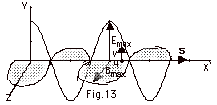
- Once the charge is in motion,
the magnetic field exerts a force on the charge to the right.
Although the magnetic force does no work, it does give the
charge momentum.
The magnetic force Fm = qvB = qvE/c, since B =
E/c for an electromagnetic wave.
Thus Fm = qvB = qvE/c = DU/cDt
or
Fm Dt
= DU/c.
Since F = Dmv/Dt
= Dp, Dp
= FDt = DU/c.
If a particle absorbs energy DU,
it acquires a momentum DU/c.
The momentum of the particle must have belonged to the wave!
- Pressure = P = Force/Area.
For a wave, since FDt
= DU/c,
F = [(DU/Dt)/c]
and
P = [(DU/Dt)]/c)Area
= [(DU/Dt)/area]/c.
Power = [(DU/Dt)].
(Power)/Area = Sav.
Thus P = Sav/c.
- Alternating Currents
- The basic problem is an analysis
of alternating current (ac) to find expressions for the current
amplitude Ip and the phase angle F
where the current I(t) = Ip sin (wt
+ F), when V(t) = Vp
sin wt is applied to a
circuit.
- Single Circuit Elements
- Resistor R only (Fig. 14a)
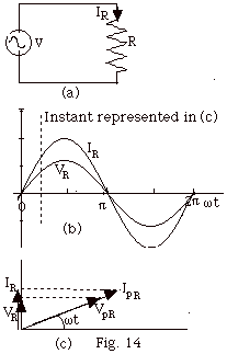
- V(t) = Vp
sin wt = VR
= IR R.
IR = Vp sin wt/R.
IR = IpR sin wt,
where IpR = VpR/R.
The current and the potential difference across R
are in phase (Fig. 14c).
- The phasor diagram is
shown in Fig. 14c for a resistive circuit only. The
maximum values for the current in R and the potential
difference across R are IpR and VpR,
respectively. The instantaneous values of the current
and the potential difference across R, IR
and VR, respectively, are shown for the
time indicated in Fig. 14b.
Notice that IR = IpR sin wt
and VR = VpR sin wt
.
- Capacitor C only (Fig. 15a)
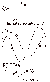
- V(t) = Vp sin
wt = VC
= q/C. q = CVC = CVpCsin
wt.
IC = dq/dt = wCVpC
cos wt =
wCVpC sin
(wt + p/2)
because
(sin wt cos p/2
+ cos wt sin p/2)
= cos pt.
IC = Ipc sin (wt
+ p/2), where
Ipc = VpC/(1/wC).
1/wC = XC.
The capacitive reactance takes the place of
R in a total resistive circuit. The current in the
capacitive circuit leads the potential difference
across the capacitor (Fig. 15b).
- The phasor diagram for
a capacitor only circuit is shown in Fig. 15c. The
maximum values for the current for C and the potential
difference across C are IpC and VpC,
respectively. The instantaneous values of the current
and the potential IC and VC
are shown at the time indicated in Fig. 15b.
Notice that IC = IpC sin (wt
+ p/2). VC
= VpC sin wt.
- Inductor only (Fig. 16a)
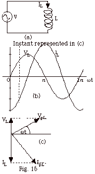
- V(t) = VpL
sin wt = VL
= L dIL/dt.
Separating variables,
VpL sin wt
dt = L dIL
(VpL / L) sin wt dt =
  dIL
dIL
- (VpL / wL)
[cos wt - 1] =
IL - IoL
IoL = - (VpL / wL)
IL (t) = - (VpL / wL)
cos wt
=
(VpL / wL)
sin (wt - p/2)
(VpL/wL)
cos wt = (VpL/wL)
sin (wt
- p/2) because
(sin wt cos p/2
- cos wt sin p/2)
= - cos wt.
IL = IpL sin (wt
- p/2), where
I pL = VpL/(wL).
wL = the inductive
reactance = XL.
The current for the inductive circuit lags the potential
difference across the inductance by p/2
as shown in Fig. 16b.
- The phasor diagram for
an inductor only circuit is shown in Fig. 16c. The
maximum values for the current in L and the potential
difference across are IpL and VpL,
respectively. The instantaneous values of the current
and the potential IL and VL,
respectively, are shown at the time indicated in Fig.
16b.
Notice in the phasor diagram IL = IpL
sin(wt
- p/2).
Vc = VpC sin wt.
- RLC Series Circuit
- The applied potential difference
across the circuit V(t) = Vp sin wt
(Fig. 17a) and the current I(t) = Ip sin (wt
- F) is the same everywhere
in the series circuit.
The potential difference across the resistor = VR(t)
= IR = [Ip sin (wt - F)]R
is in phase with the current (Fig. 17b and Fig. 18b).
The potential difference across the inductor = VL(t)
leads the current by p/2
(Fig. 17c and Fig. 18b). VL(t) = [Ip
sin (wt - F
+ p/2)]wL.
The potential difference across the capacitor VC(t)
lags the current by p/2
(Fig. 17d and Fig. 18b). VC(t) = [Ip
sin (wt - F
- p/2)](1/wC)
- In Fig. 18c,
Vp2
= VpR2 + (VpL –
VpC)2
Vp2 = (IpR}2
+ (IpwL –
Ip/wC)2
Ip = Vp/[R2 +(wL
–1/wC)]1/2
= Vp/Z
tan F = (wL
–1/wC)]/R
- Phasor Diagrams Revisited
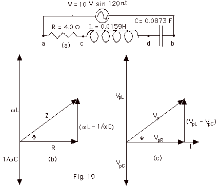
- While the previous phasor
diagrams allow you to take projections and find the voltage
or current at any time, you can simplify the diagrams
by drawing them as shown in Fig. 19 b and c above.
- Draw R and I along the +X-axis,
wL along the +Y-axis,
and 1/wC along the
–Y axis (Fig. 19b)
- Since I is the same in the
resistance, inductance, and capacitance
(Fig. 19c),
- VpR is drawn
along the +X-axis because VR is in phase
with I.
- VpL is drawn
along the +Y-axis because VL leads I by
p/2.
- VpC is drawn
along the -Y-axis because VC lags I by
p/2.
- From Fig. 19b, tan F
= (wL –
1/wC)/R.
- From Fig. 19c,
Vp =
[VpR2 + (VpL2
– VpC2)]1/2
Vp = {(IpR)2
+ [(IpwL)2
– (Ip/wC)2]}1/2
or
Ip = Vp/[R2 + (wL
– 1/wC)2]1/2
- For the circuit of Fig. 19a,
Vp = 10 V, w
= 120ps-1,
R = 4.0 W, L = 0.0159
H, and C = 0.884 mF.
XL = wL = 6.0
W
XC = 1/wL =
3.0 w
Ip = Vp/[R2 + (wL
– 1/wC)2]1/2
= 10 V/[16 + (6 – 3)2]1/2 W
= 2.0 A
VpR = IpR = 8.0 V
VpL = Ip (XL) = 12 V
VpLc= Ip (Xc) = 6 V
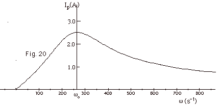
- The maximum value of Ip
occurs for wL =
1/wC, or the resonant
frequency wo
= 1/(LC)1/2. At resonance, Ip
= Vp/[R2 + (wL
– 1/wC)2]1/2
= Vp/R. The resonance curve for the circuit of
Fig. 19a is shown in Fig. 20 below.
- Power = IV
= [Ip sin
(wt - F)][Vp
sin wt}
= IpVp [sin wt
cos F - cos wt
sin F)[sin wt]
= IpVp [sin2 wt
- cos wt sin wt]
= IpVp [sin2 wt
cos F – 1/2(sin
2wt](sin F)
The average value of sin2
wt is 1/2 and the average
value of sin 2wt is 0.
Pav = (IpVp /2) cos F.
Because cos F =
R/[R2 + (wL
– 1/wC)2]1/2,
Pav = (Ip2/2)R = I2rms
R, where the root-mean-square value of the current is
defined as Ip/(2)1/2 and the root-mean-square
value of the voltage is defined as Vp/(2)1/2.
- Sample problems in 108
Problem Set for Induction: 22-26.
|
|