|
|
|
1.
|
- The average current density is
J = I/A = 20A/p(1.63
x 10-3 m)2 = 2.4 x 10⁶
A/m2.
- vd = J/en = 2.4 x 10⁶ A/m2/(1.6
x 10-19C)(8.47 x 1028 m-3)
=
1.8 x 10⁻⁴ m/s.
- E = rJ = (1.56 x 10⁻⁸
V-m/A)(2.4 x 106 A/m2) = 0.037 V/m.
- R = rL/A or
L = RA/r = 0.012 W (1.2
x 10-6 m2)/1.56 x 10-8 W - m
= 0.92 m.
|
|
|
2.
|
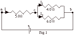
If the current I1 = 3.0 A in the 4.0 W
resistor,
Vcb = I1 (4.0 W)
= 3.0 A(4.0 W) = 12 V.
I2 = Vcb/6.0 W
= 12 V/6.0 W = 2.0
A.
I = I1 + I2 = 3.0 A + 2.0 A = 5.0 A.
Vac = IRac = (5.0 A)(5.0 W)
= 25 V.
Vab = Vac + Vcb = 25 V +
12 V = 37 V.
|
|
|
3.
|
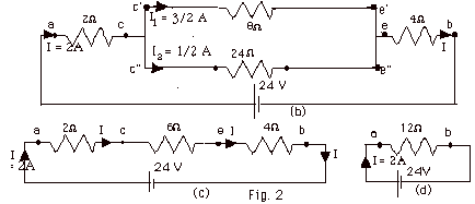
- Rc’e’ = (2 + 6) W
= 8 W.
- 3 W is in series with
the 21 W. Rc”e”
= (3 + 21) W = 24 W.
- Rc’e’ is in parallel with Rc”e”.
1/Rce = (1/8 + 1/24)W-1
= (3/24 + 1/24) W-1.
Rce = 6 W.
- Rab = Rac + Rce + Reb
= (2 + 6 + 4) W = 12
W.
- I = Vab/Rab = 24 V/12 W
= 2 A.
- Vce = IRce = 2A(6 W)
= 12 V = Vc’e’ = Vc”e”.
- I1 = Vc’e’/Rc’e’
= 12 V/ 8 W = 3/2 A.
- I2 = Vc”e”/Rc”e”
= 12 V/24 W =
1/2 A. Note that I1 + I2
= I.
|
|
|
4.
|
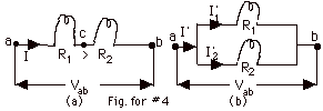
For the resistors in series, the current in each is the same
and the power
P = I2R. Since R1 > R2,
P1 > P2.
When the resistors are in parallel, the current is not the same
in each, but the potential difference across each is the same.
P1 = (I1’) Vab
= (Vab/R1)(Vab) = Vab2/R1.
P2 = (I2’) Vab = (Vab/R2)(Vab)
= Vab2/R2.
Since R1 > R2, now P2
> P1.
|
|
|
5.
|
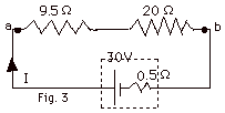
- The total resistance of the circuit is (9.5 + 20 + 0.5)W
= 30 W.
The current I = 30 V/30 W=
1 A.
- Power dissipated in external resistances =
I2(9.5 + 20)W
= 1 A2 (29.5 V/A) = 29.5 W.
Power dissipated in the internal resistance =
I2(0.5 W)
= (1 A2) (0.5 V/A) = 0.5 W.
Total power dissipated in resistances =
(29.5 + 0.5) W = 30 W.
- Power supplied when chemical energy is changed into electrical
energy = (Emf)(I) = 30 V (1 A) = 30 W.
|
|
|
6.
|
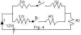
- When both switches are closed, the resistance of the upper
branch of the parallel circuit is (2 + 1) W =
3W and that of
the lower branch is
(2 + 4) W = 6W.
For the parallel group, 1/Req = 1/3 W +
1/6 W and
Req = 2W.
The total resistance of the circuit is (2 + 4) W
= 6 W and
I = 12 V/6 W = 2 A.
- If only switch A is closed, the bottom part of the parallel
grouping is not in the circuit. The total resistance of
the circuit is (2 + 1 + 4) W
and
I = 12/7 A.
- If only switch B is thrown, the top part of the parallel
grouping is not in the circuit. The total resistance of
the circuit is (2 + 4 + 4)
W and
I = 12V/10 W = 1.2 A.
|
|
|
7.
|
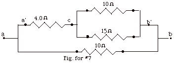
In the Fig. for #7, the 10 W
resistance is wired in parallel with the 15 W
resistance from c to b’. This parallel grouping is then
wired in series with 4.0 W
resistor between a’ and b’. Finally this grouping
is wired in parallel with another 10 W
resistor.
1/Rcb’ = 1/10 W
+ 1/15 W = (3 +2)/30 W.
Rcb’ = 6 W.
Rab’ = (6 + 4) W
= 10 W.
1/Rab = 1/10 W
+ 1/10 W = 2/10
W.
Rab = 5.0 W
|
|
|
8.
|

For the circuit in Fig. for #8 above, I= e/(r
+ R).
For I = 6.0 A and R = 2.0 W,
6.0 A = e/(r
+ 2.0 W)
(Equation
1)
For I = 3.0 A and R = 7.0
W,
3.0 A = e/(r
+ 7.0 W)
(Equation
2)
From Eq. 1: e = 6.0A
r + 12 V. From Eq. 2: e
= 3.0A r + 21V.
Thus, 6.0A r + 12 V = 3.0A r + 21 V. r = 9.0V/3.0
A = 3.0 W.
Substituting r back into Eq. 1, 6.0 A = e/(3.0
+ 2.0) W. e
= 30 V.
|
|
|
9.
|
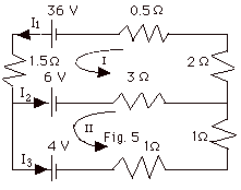
From conservation of charge,
I1 = I2 + I3 or
I3 = I1 - I2
(Equation
1)
For loop I,
36 V - I1(0.5 + 2 + 1.5)
W- 6 V - I2(3 W)
= 0 or
30 A = 4I1 + 3I2
(Equation
2)
For loop II,
6 V + (3 W)I2
- 4 V - (2 W)I3 =
0 or
2A = 2I3 - 3I2 (Equation
3)
Substitute Eq. (1) into Eq. (3):
2A = 2(I1 - I2) -3I2
or
2A = 2I1 - 5I2
(Equation
4)
2 x Eq. 4 equals: 4A
= 4I1 - 10I2
(Equation
5)
Eq. 2 - Eq. 5 equals: 26A
= 13I2 or
I2 = 2A.
Then from Eq. 2: 30A
= 4I1 + 3(2A) and
I1 = 6 A.
From Eq. 1, I3 = 6A - 2A = 4A.
|
|
|
10.
|
Given q(t) = Qi e-t/RC. When t =
RC, q (RC) = Qi e -RC/RC = Qi
e-1 = Qi/e.
The time constant for the circuit is RC.
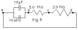
- In Fig. 6 above, the two capacitors are in parallel. For
capacitors in parallel, the equivalent capacitance is the
sum of the capacitances.
Cab = (10 + 10)µF = 20µF
= 20 x 10-6 C/V.
The two resistances are in series. The equivalent resistance
of resistances in series is the sum of the resistances.
Rbd = (5.0 + 2.0)MW=
7.0 MW = 7.0 x 10⁶
V/A.
The time constant =
RC = 7.0 x 10⁶ V/A x 20 x 10-6
C/V = 140 C/A = 140 s.
- q(t) = Qie-t/RC. For Qi
= 100 µC and q = 50µC, q/Qi
= 1/2 = e-t/RC
or
et/RC = 2. Taking log of both sides of
this equation, t/RC = ln 2.
t = RC ln 2 = 140 s (0.693) = 97 s.
|
|
|
11.
|

- Vab = Vac + Vcb
e = q/C + RI =
q/C + Rdq/dt.
q - eC = - RC dq/dt,
or
separating variables
dq/(q - eC) = - dt/RC.
Integrating,
Qo ∫q dq/(q - eC)
= -1/RC o∫t dt
ln (q - eC)/(Qo
- eC) = - t/RC.
Taking the antilog of both sides of the equation and rearranging,
q(t) = Qo e-t/RC + eC(1
- e-t/RC ).
I(t) = dq/dt = - Qo/RC e-t/RC +
e/R e-t/RC.
q(0) = Qo = C(Vac)o =
4.0 x 10⁻⁶ C/V(100 V) = 4.0 x 10⁻⁴
C.
I(0) = - Qo/RC + e/R
= (-100 + 40)V/500 W
= 0.12 A.
- q(∞) = eC =
40 V(4.0 x 10⁻⁶ C/V) = 1.6 x 10⁻⁴C.
I(∞) = 0.
|
|
|
12.
|
The current in the circuit of Fig. for #12a above, I =
e/(r + R), and the power
delivered to the load resistor R, is P = I2R = e2R/(r
+ R)2.
For maximum power,
dP/dR = e2[(r
+ R)2 -2R(r + R)]/(r + R)4 = 0,
so
[(r + R)2 -2R(r + R)] = 0 or
r + R = 2R and
R = r.
Again P = e2R/(r
+ R)2. For R = 0, P = 0. As R approaches
a very large number, P approaches e/R
which goes to zero. In the Fig. for #12 b above, I have
taken e = 2.0 V and
r = 0.5 W. Notice
that P is a maximum at R = r = 0.5 W.
|
|
|
13.
|
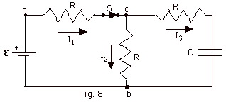
- Just after the switch is thrown, the capacitor has no
charge. It is just as though there were a short in the circuit
or replacing the capacitor by a wire. Then the two resistance
between points c and b are in parallel.
(See Fig. 8b below).
1/Rcb = 1/R + 1/R = 2/R and Rcb =
R/2. This equivalent resistance Rcb is in series
with the resistance R between a and c. (Fig. 8c below).
The total resistance of the circuit =
RAB = R + R/2 = 3R/2 = 3(2000 W/2)
= 3000 W (Fig.
8d below).
I1 = e/Rab
= 6 V/3000 W =
2 x 10⁻³ A.
Vac = I1(R/2) = 2 x 10⁻³
A(1000 W) = 2 V.
I2 = I3 = Vac/R = 2 V/2000
W = 1 x 10⁻³
A.
Notice that I1 = I2 + I3.

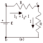
- After the switch has been thrown for a very long time,
the capacitor is fully charged and acts like an open circuit.
The circuit reduces to that shown in Fig. 8e below.
I3 = 0 and
I1 = I2 = I = e/2R
= 6 V/2000 W = 3 x 10⁻³A.
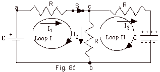
From conservation of charge,
I1 = I2 + I3 (Equation
1)
From conservation of energy,
Loop I: e
- I1R – I2R = 0
(Equation
2)
Loop II: I2R –
I3R - q/C = 0 (Equation
3)
Substituting Eq. 1 into Eq. 2:
e - (I2
+ I3)R – I2R = 0
(Equation
4)
Solving for I2 in Eq. 4:
I2 = (e
- I3R)/2R
(Equation
5)
Substituting Eq. 5 into Eq. 3:
(e - I3R)/2
– I3R + q/C = 0
(Equation
6)
Rearranging Eq. 6:
e = 3I3R
+ 2q/C (Equation
7)
Recognizing that I3 = dq/dt, Eq. 7 becomes
:
e = 3(dq/dt)R
+ 2q/C (Equation8)
The equation we solved for in the Outline for Circuits was
e = (dq/dt)R
+ q/C (Equation
9)
and had solution q(t) = Ce(1
– e-t/RC) and time constant t
= RC.
Comparing Eq. 8 and Eq. 9, we see for Eq. 8 that e
becomes e/2
and the time constant t
= 3RC/2.
For this case,
q(t) = (Ce/2)(1
– e-2t/3RC) and
I3(t) = dq/dt = (e/3R)
e-2t/3RC (Equation
10)
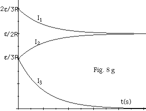
I3(0) = (e/3R)
e0 = (e/3R)
and
I3(∞) = 0, as in Part (b) above.
From Eq. 5,
I2 = (e
- I3R)/2R = e/2R
- I3/2 = e/2R
- (e/6R) e-2t/3RC
I2(t) = e/6R(3
- e-2t/3RC) (Equation
11)
I2(0) = e/3R
and
I2(∞) = e/2R,
as in Part (b) above.
From Eq. (1),
I1 = I2 + I3 =
(e/6R)(3 - e-2t/3RC)
+ (e/3R) e-2t/3RC
I1(t) = (e/6R)
(3 + e-2t/3RC)
(Equation
12)
I1(0) = (2e/3R)
and
I1(∞) = (e/2R),
as in Part (b) above.
A plot of I1, I2, and I3
as a function of time is shown in Fig. 8g below.
|
|