|
|
|
1.
|

FB = B .
A = BA cos 0o = BA.
e = - DFB/Dt
= - (DB/Dt)A
= - [(0.040 - 0.080)N/A-m/(2.0 s)]4.0
m2
= 0.080 N-m/C
= 0.080 V.
I = e/R = 0.080 V/0.04 W
= 2 A.
With the magnetic field into the page and decreasing, the sense
of the current will be such to oppose the change that produced
it, or clockwise. A clockwise-induced current produces a magnetic
field into the page and opposes the decreasing external magnetic
field into the page.
|
|
|
2.
|
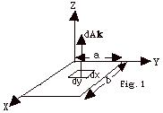
dFB = B .
dA = 0.0120 N/A-m2(x sin wt
j + y cos wt k)
. dA k
=
0.0120 N/A-m2 y cos wt
(dx dy), where w =
103 s-1.
FB = 0.0120
N/A-m2 cos wt
o∫b dx o∫a
y dy
= 0.0120 N/A-m2
cos wt (ba2/2)
e = - dFB/dt
= 0.0060 N/A-m2 w sin
wt (ba2)
=
0.0060 N/A-m2 (103 s-1)sin
103 s-1t(0.0015 m3)
=
9.0 x 10⁻³ V sin 103 s-1t
=
9.0 mV sin 103 s-1t.
|
|
|
3.
|
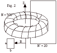
For a toroid, all the flux is confined to the inside of the
toroid.
B = NµoI/2pr.
FB = ∫
B . dA = NµoI/2p
o∫a dz R∫R
+ b dr/r
= (NµoI/2p)a
ln (R + b)/R
= (NaµoIo
sin wt/2p))
ln (R + b)/R.
e = - N’ dFB/dt
= - wNN’[a(µo/2p)Io
cos wt)]ln (R + b)/R
= 12p
x 105 s-1(0.02m)(2 x 10⁻⁷N/A2)(50
A){ln(6 + 3)/6} cos 120p
s-1 t
= 0.306 V cos 120p
s-1 t.
|
|
|
4.
|

B = µonI.
FB = ∫
B . dA = µonI(pR2)
= µon[30 A (1
- e -1.6t/s)](pR2).
e = - N dFB/dt
= µoNn(1.6/s)30 A(e -1.6t/s)(pR2)
= (4 x 10⁻⁷ N/A2)(250)(400/m)(1.6/s)(30
A)(e -1.6t/s)p(0.06
m)2
= 2.17 x 10⁻² (e -1.6t/s)V.
|
|
|
5.
|
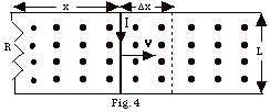
- The initial magnetic flux (FB)i
= B(area) = B(xL).
- The later magnetic flux = B(x + Dx)L.
The change in flux = DF=
BL{(x + Dx) -x} = BLDx.
- The electromotive force = e =
DF/Dt
= BL(Dx/Dt)
= BLv.
- I haven't used the minus sign because we find the sense
of the current from Lenz's law. The sense of the induced
current is such to oppose the change that produces it. As
the rod moves to the right, the magnetic flux out of the
page increases. To oppose this, the induced current must
be clockwise. A current clockwise will produce a field into
the page. If you curl the fingers of your right hand clockwise,
your thumb points into the page.
- The current I = e/R
= BLv/R.
- Power dissipated in the resistance R = I2R
= (BLv/R)2R = B2L2v2/R,
since I = e/R = BLv/R.
- In Fig. 4 above, the induced current is clockwise, which
means positive charge moves down through the bar of length
L. The force on the current carrying bar due to the magnetic
field B is Fm = I( L x B).
L is taken in the direction of the current or down.
B is out of the page, so Fm can
be neither in or out nor up or down. It must be to the right
or the left. If you rotate vector L into vector B,
you find Fm is to the left. The external
agent must exert a force F equal in magnitude to Fm
to move the rod with a constant velocity. F
= Fm = ILB sin 90o = ILB = (BLv/R)LB
= B2L2v/R.
- Power = work/time = (force x distance)/time = force x
(distance/time) = force x v. Power generated by external
agent = (B2L2v/R)v = B2L2v2/R.
- Notice that the answers to (f) and (h) are the same, as,
of course, they should be if you believe in conservation
of energy and all those good things. The external agent
must do work in order to produce the induced emf and current.
Lenz's law is just a statement of conservation of energy.
|
|
|
6.
|

- As the bar slides down, the magnetic flux into the page
increases. To oppose this, the induced current must be to
the right in the bar. The induced current then produces
a magnetic field out of the page inside the loop.
- The "motional emf" = BLv. I = e/R
= BLv/R. The magnetic force on the bar of length L
is Fm = (I)LB sin 90o = (BLv/R)LB(1)
= B2L2v/R. For a current to the right
in a field into the page the force on the bar is up. For
constant velocity, Fnet = B2L2v/R
- mg = 0 and v = mgR/B2L2
= 0.50 kg(9.8 m/s2)(0.01 N-m/A-C)/(0.20
N/A-m)2(0.5 m)2 = 4.90 m/s.
|
|
|
7.
|


After 1 s, one-half of the loop is in the magnetic field so
the magnetic flux = BA = (1T)(0.5m2) = 0.5 Wb.
After 2 s, the entire loop is in B: FB
= 1 Wb.
From t = 2s to t = 10 s, the entire
loop is in the field.
At t =10 s, the front edge of the loop reaches the edge
of the field boundary.
At t = 11 s, only half the loop is in the field, and
at t = 12 s none of the loop is in the field.
From t = 12 s on the flux is zero.
Since the emf = - dFB/dt,
you find the emf from the negative slope of the
FB vs t
graph, as shown in the figures above. As the loop enters
the magnetic field, the sense of the induced current is clockwise
in the loop producing a magnetic field into the page to oppose
the change that produced it. As it leaves the field,
the current is counterclockwise.
From t = 0 to t = 2 s, and from t
= 10 s to t = 12 s,
I = e/R = 0.50 V/0.01W
= 50 A.
From t = 2s to t = 10 s, I = 0.
|
|
|
8.
|

- dF = B . dA
= (Bo N/A-m – C N/A-m3-s2
r2t2)k • 2pr
dr
=
2p(Bor N/A-m
– C N/A-m3-s2 r3t2)dr
- F = o∫R
2p(Bor N/A-m
– C N/A-m3-s2 r3t2)dr
= Bo p
R2 N/A-m - pCR4t2
N/A-m3-s2 /2
- e = - dF/dt
= pC N/A-m3-s2
R4t
- C is a positive constant. As time increases, the second
term in B increases. Since this is a negative term, the
magnetic field, which is up, is decreasing with time, the
induced current must produce a magnetic field up. If you
point the thumb of your right hand up and view your curled
fingers from above, you see the current is counterclockwise.
|
|
|
9.
|
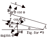
dFB = B
. dA = B xL cos Q
e = - dFB/dt
= - B (dx/dt)L cos Q
= - BvL cos Q
I =e/R = BvLcos Q/R
Fm = I(L x B)
Fm = ILB sin 90o = ILB = [BvL
cos Q/R](LB) = (BL)2v
cos Q/R
The direction of the magnetic force is to the left. The component
of the magnetic force up the plane equals
Fm cos Q
= [(BL)2v cos Q/R]cos
Q= (BL)2 v
cos2 Q/R.
The component of the gravitational force down the plane = mg
sin Q.
For a constant velocity, Fnet = mg sin Q
- (BL)2 v cos2 Q/R
= 0 or
v = mgR sin Q/(BL cos Q)2.
|
|
|
|
|
11.
|
- The magnetic field inside the solenoid is B = µonI.
The number of loops in a length l
is nl; each loop has
a flux pR2B,
where R is the radius of the solenoid. The flux through
all the loops in a length l
is FB = pR2µon2Il.
The inductance L = FB/I
= pR2µon2l.
The inductance per unit length is pR2µon2.
- L = pR2µon2l=
p(2 x 10⁻² m)2(4px
10-7 N/A2)(2 x 103 m-1)2(1
m)
= 6.32 x 10⁻³ V/(A/s) = 6.32 x 10⁻³
V/(A/s) = 6.32 x 10⁻³ H.
- Emf = LdI/dt = 6.32 x 10⁻³ V/(A/s) (3.0 x
102 A/s) = 1.9V.
|
|
|
|
|
13.
|
For build up of the current I(t)
= (Emf/R) (1 - e-Rt/L).
As t approaches a very large number, e-Rt/L
approaches zero and
I = Imax = (Emf)/R or
R = (Emf)/Imax = 3.0V/24 A= (1/8) W.
For decay of the current, I(t) = Imax e-Rt/L.
I(0.22s) = 12A = 24 A e-(1/8 W)(0.22s)/L.
(1/8 W)(0.22 s) =2.75 x
10-2 (V/A)s.
12A = 24 A e-0.0275 (V/A)s/L
or 12/24
= 1/2 = e-0.0275(V/A)s/L.
Taking reciprocals of both sides of the equation, 2 = e+0.0275(V/A)s/L.
Taking the ln of both sides of the equation gives ln 2 = 0.0275(V/A)s/L.
L = 0.0275 (V/A)s/ln 2 = 40 x 10-3 V/(A/s) = 40 mH.
|
|
|
14.
|

(a) UE = 1/2 q2/C = 1/2 (1.0 x10⁻⁴
C)2/(5.0 x 10-6C/V) = 1.0 x 10⁻³
J.
(b) and (c)
q/C + L dI/dt = 0 or
L d2q/dt2 + q/C = 0 and
d2q/dt2 + (1/LC)q = 0.
Compare with d2x/dt2 + (k/m)x = 0
and see that for q = maximum q = qm at t = 0,
q(t) = qm cos 2pt/T
with T = 2p (1/LC)1/2
= 2p [1/(5.0 x 10-2
V-s/A)(1.0 x 10-4 C/V)]1/2
= 2.8 x 10³ s.
I(t) = Im sin 2p/T.
The electric energy UE = q2/2C is a maximum
at t = 0, t = T/2, t = T, and so forth.
The magnetic energy UB = 1/2 LI2 is a
maximum at t = T/4, t = 3T/4, t = 5T/4, and so forth.
|
|
|
|
|
|
|
17.
|
- S = 1/µo (E x B).
c = 1/(µoeo)1/2.
eoc2
= 1/µo.
Thus S = eoc2
(E x B).
- uE = 1/2 eoE2
and
uB = B2/2µo.
B = E/c.
uB = E2/2c2µo
= 1/2 eoE2
= uE
- Sav = 1/µo (EmBm/2)
= 1/µo
(Em2/2c)
= (1/2cµo)(Em2)
= [1/(2 x 3 x
108 m/s x 4p
x 10-7 N/A2)](Em2)
= [1.33 x 10⁻³
A2-s/N-m](Em2).
|
|
|
18.
|
- VR = IR = EL or
E = IR/L. B = µoI/2pr.
- S = 1/µo (EB) = 1/µo(µoI2R/2prL)
= (I2R/2prL).
- Power = Energy/second = S (surface area) = (I2R/2prL)(2prL)
= I2R.
|
|
|
19.
|
- Average Intensity = Energy/area =
7.0 W/(p)(5 x 10-4
m)2 = 8.9 x 10⁶ W/m2 =
8.9 MW/m2.
- Sav = 1/2cµo (Em2).
Em = (2µocSav)1/2
= (2 x 4p
x 10-7 N/A2 x 3 x 108 m/s
x 8.9 x 10⁶ N/m-s)1/2
= 8.2 x 10⁴
N/C.
|
|
|
|
|
21.
|
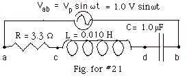
- The resonance frequency equals
w0
= 1/(LC)1/2
= 1/[(0.010 V-s/A)(1.0 x
10-6 C/V)]1/2
= 104 Hz
= 104 s-1
- At resonance, maximum current Ip = Vp/R
= 1.O V/3.3 W = 0.30
A
- At resonance, average power dissipated
Pav = 1/2 (Ip)2R
= [1/2R](Vp)2
= [1/2(3.3
V/A)](1.0 V)2
= 0.15
W
- When w = 0.95w0,
X = XL - Xc = wL
- 1/wC =
(9500 s-1)(0.010 V-s/A) - [1/(9500 s-1)(1.0
x 10-6 C/V) = - 10.3 W
The impedance Z = [R2 + X2]1/2
= [3.22 + (-10.3)2]1/2
w = 10.8 W.
The maximum current Ip = Vp/Z = 1.0V/10.8
W = 0.093 A,
approximately 1/3 of the maximum current at resonance.
Average power dissipated =1/2(Ip)2R
= (1/2)(Vp2/Z)R/Z
= (1/2)(Vp2/Z)cos F, where
F is the phase angle
with tan F
= X/R = (-10.3 w)/3.3
W = 1.26 and F
= - 1.26 rad = - 72.40.
Average Power = 1/2(1.0 V2/10.8 V/A)cos (72.4o)
= 0.014 W,
which is about 10% of the average power at resonance.
|
|
|
22.
|
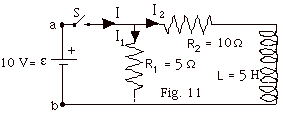
Notice that the potential difference Vab always equals
10 V. While the switch is closed, the potential difference across
R1 and the series circuit of R2 and L
will always be 10 V.
When the switch S is just closed,
- I1 = 10V/5 w=
2 A.
- Since the current has not started to build up, I2
= 0.
- I = (2 A + 0) = 2 A. Since I2 = 0,
the potential difference across R2 = 0.
- Since Vab = 10 V and VR the potential
difference across R2 = 0,
the potential difference VL across the inductor
= 10 V.
- L dI2/dt = VL or
dI2/dt = VL/L = 10 V/ 5 V-s/A = 2
A/s.
Note 1 H = V-s/A.
After a very long time, I2 has reached a constant
maximum of
10 V/R2 = 10 V/10 W
= 1 A, and dI2/dt = 0. So the answers
are now:
(a) As always, I1 = 2 A.
(b) I2 = 1 A.
(c) I = 3A.
(d) VR = I2 R2 = Vab
= 10 V.
(e) L dI2/dt = VL = 0, because
- dI2/dt = 0.
|
|
|
23.
|

In general, Ip = Vp in/[(R2
+ (XL – XC)2]1/2.
When there is no capacitor in the circuit,
Ip = V p in/(R2
+ XL 2)1/2
= Vp in /[R2
+ (wL) 2]1/2.
- For Fig. 12a above, Vp out = Ip
(wL) = {Vp in/[R2
+ (wL) 2]1/2}(wL).
Dividing numerator and denominator by (wL),
Vp out = {Vp in/[(R/wL)2
+ 1]1/2 or
Vp out / Vp in = 1/[(R/wL)2
+ 1]1/2.
For small values of w,
(R/wL)2 is
very large and Vp out / Vp in is very
small.
For large values of w,
(R/wL)2 is
very small and Vp out / Vp in approaches 1.
The sketch of Vp out / Vp in vs.
w in Fig. b below describes
this case.
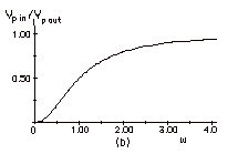
Since the effect of small frequencies is small, this is
called a high frequency pass filter.
- For Fig. 12b above, Vp out = Ip
(R) = {Vp in/[R2 + (wL)
2]1/2}(R).
Dividing numerator and denominator by (R),
Vp out = {Vp in/[1 + (wL/R)2
]1/2 or
Vp out / Vp in = 1/[1 + (wL/R)2
]1/2.
For small values of w,
(wL/R)2 is
very small and Vp out / Vp in approaches 1.
For large values of w,
(wL/R)2 is
very large and Vp out / Vp in
approaches 0.
The sketch of Vp out / Vpi in vs.
w in Fig. a below describes
this case.
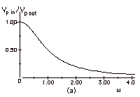
Since the effect of large frequencies is small, this is
called a low frequency pass filter.
|
|
|
24.
|

In general, Ip = Vp in/[(R2
+ (XL – XC)2]1/2.
When there is no inductor in the circuit,
Ip = Vp in / (R2
+ XC2)1/2
= Vp out /
[R2 + (1/wC)
2]1/2.
- For Fig. 13a, Vp out = Ip (1/wc)
= {Vp in / [R2 + (1/wC)
2]1/2}(1/wC).
Multiplying numerator and denominator by (wC),
Vp out = {Vp in / [(RwC)2
+ 1]1/2 or
Vp out / Vp in = 1/[(RwC)2
+ 1]1/2.
For small values of w,
(RwC)2 is
very small and Vp out / Vp in approaches 1.
For large values of w,
(RwL)2 is
very large and Vp out / Vp in approaches 0.
The sketch of Vp out / Vp in vs.
w in Fig. a below describes
this case.

Since the effect of large frequencies is small, this is
called a low frequency pass filter.
- For Fig. 13b, Vp out = Ip (R)
= {Vp in / [R2 + (1/wC)
2]1/2}(R).
Dividing numerator and denominator by (R),
Vp out = {Vp in / [1 +(1/RwC)2
]1/2 or
Vp out / Vp in = 1/[1 + [(1/RwC)2
]1/2.
For small values of w,
(1/RwC)2
is very large and Vp out / Vp in
approaches 0.
For large values of w,
(1/RwL)2
is very small and Vp out / Vp in
approaches 1.
The sketch of Vp out / Vp in vs.
w in Fig. b below describes
this case.

Since the effect of small frequencies is small, this is
called a high frequency pass filter.
|
|
|
25.
|
- Pav = I2rms R = V2rmsR/(R2
+ (wL – 1/wC)2).
Since wo2
= 1/LC, (wL
– 1/wC)2
= (L2/w2)(w2
- wo2)2.
Pav = V2rmsR/[R2
+ (L2/w2)(w2
- wo2)2]
= V2rmsRw2/[(Rw)2
+ (L2)(w2
- wo2)2].
- At resonance, w =
wo, Pav
at resonance = V2rms / R.
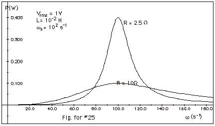
- A plot of Pav as a function of w
is shown below in Fig. for #25:
- V2rmsRw2
/ [(Rw)2
+ (L2)(w2
- wo2)2]
= V2rms / 2R
2R2w2
= (Rw)2 +
(L2)(w2
- wo2)2
R2w2
= (L2)(w2
- wo2)2
±Rw = L(w2
- wo2)
w2 ±
Rw/L - wo2
= 0
w = ±R/2L ±
[(R/2L)2 + wo2]1/2
whigh = R/2L
+ [(R/2L)2 + wo2]1/2
wlow =
- R/2L + [(R/2L)2 + wo2]1/2
whigh
- wlow =
Dw = R/L
- Qo = wo/Dw=
woL/R
|
|
|
26.
|
Ip = Vp/[(R2
+ (XL – XC)2]1/2.
At resonance,
Ip = Vp/R.
VpL = Ip (woL)
= (Vp/R)(woL)
= (10 V/10 W)(woL).
wo = (1/LC)1/2.
(woL) = (L/C)1/2
= [(1.0 V-s/A/1.0 x 10-6 C/V)]1/2 = 103
W.
VpL = (Vp/R)(woL)
= (10 V/10 W)103
w= 103 V.
|
|