|
Answers - Magnetic Fields
|
|
|
1.
|
Fm(N) = q (C) v(m/s) B sin
 v,
B. v,
B.
The unit of B is then N/(C-m/s) or
N/(C/s-m) = N/A-m.
So 1 T = 1 N/(C/s-m) = 1 N/A-m.
|
|
|
2.
|
With Fm = q(v x
B), Fm is always perpendicular to v
and to B and to the plane that contains v and
B, but the angle between v, B ( v,
B) can have any value. v,
B) can have any value.
|
|
|
3.
|
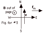
Let the magnetic field B be out of the page, south
be down and north be up in the plane of the page so that v
is up. The  v,
B = 900. v,
B = 900.
- Fm = qvB sin 90o = 1.6 x 10⁻¹⁹
C(3.2 x 10⁷ m/s)(1.2 x 10-3
N/C/s-m)(1) = 6.1 x 10⁻¹⁵ N.
- If you point the fingers of your right hand up (in the
direction of v) and then curl them toward B
(out of the page), your thumb points to the right or to
the east.
|
|
|
|
|
|
|
6.
|
Fm =
qvB sin  v,B
= (10-6 C)(103 m/s)(2 N-s/C-m)(0.50) =
10-3 N. v,B
= (10-6 C)(103 m/s)(2 N-s/C-m)(0.50) =
10-3 N.
|
|
|
7.
|

- In Fig. for #7a above, with the velocity v parallel
to the magnetic field B,
 v,B
= 0 and sin 0o = 0, so there is no force on the
electron. The electron continues to move with velocity v
into the page. v,B
= 0 and sin 0o = 0, so there is no force on the
electron. The electron continues to move with velocity v
into the page.
- In Fig. for #7b above, the velocity v is perpendicular
to the magnetic field B,
 v,B
= 90o and sin 90o = 1. At the
instant shown in the figure, the magnetic force Fm
is down. v,B
= 90o and sin 90o = 1. At the
instant shown in the figure, the magnetic force Fm
is down.
Note: the force on a negative charge is opposite to that
on a positive charge. Since this force is perpendicular
to the velocity, it does not change the magnitude of the
velocity, but it changes its direction. As the direction
of the velocity changes, the direction of Fm
changes so it always remains perpendicular to the
velocity and the path is a circle.
- At some other angle with the magnetic field, the electron
will continue to move with constant speed in the direction
of the component of B which is parallel to velocity
of the electron and proceed in a circle from the force due
to the component of B which is perpendicular to the
velocity of the electron. The resultant path is a spiral.
- There is an acceleration of the electron in parts (b)
and (c).
|
|
|
8.
|
| Fnet = ma |
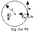 |
| qvB sin 90o
= mv2/r or
v = qBr/m |
| vA = qBrA/m
and
vB = qBrB/m |
| v = 2pr/T,
where T is the period of the motion. |
| vA = 2prA/TA
= qBrA/m. TA = 2pm/qB |
vB = 2prB/TB
= qBrB/m. TB = 2pm/qB
= TA.
|
|
|
|
9.
|
From #8, r = mv/qB. r2 = m2v/qB.
r1 = m1v/qB. m2/m1
= r2/r1 = 22/20.
|
|
|
10.
|
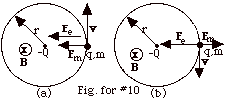
- Fe = kQq/r2 = 9.0 x10⁹
N-m2/C2(10-4 x 2 x 10-5)C2/104m2 =
18 x 10-4 N from q to - Q.
- Fm = qvB sin 90o = 2 x 10⁻⁵(4)N-s/m
v
- If the particle moves
- clockwise
the magnetic force is away
from the center of the circle
(Fig. for #10b) and
- counterclockwise
the magnetic force is toward
the center of the circle (Fig. for #10a).
-
Fnet = ma
Using Fm into the center and positive
as in Fig. for #10a,
kQq/r2 + qvB = mv2/r or
mv2/r - qBv - kQq/r2 = 0.
v = {(qB) ± [(qB)2 + 4mkqQ/r3]1/2}/2m/r
v = 
v = {8 ± [784]1/2}m/s/2
= {8 ± 28}m/s/2 = 18 m/s or
-10 m/s.
The velocity of 18 m/s corresponds to counterclockwise motion
of the particle and the negative velocity of 10 m/s to clockwise
motion of the particle.
|
|
|
11.
|
- As the positive particle with charge +q, mass m, and velocity
vo down enters Region 1 with an electric
field E to the right (the positively charged particle would
be urged from the positive plate toward the negative plate),
it experiences an electric force Fe to the right
equal to qE. In order for the +q to pass through the electric
field with no deflection, there must be a magnetic force
Fm to the left. This magnetic force must be perpendicular
to the magnetic field B and to the velocity vo.
For vo down and Fm to
the left, B cannot be up or down or to the
right or left because B is always perpendicular to
Fm and in this problem B is said
to be perpendicular to v. B must be
out of the page because only then will rotating v
into B give Fm to the left. Fm
= q(vo x B). Since
we are told that B is perpendicular to vo,
 vo,
B = 90o and sin 90o = 1. Thus,
Fm = qvoB. For no deflection,
Fnet = ma = 0 because a = 0. Taking to the right
to be positive, qE - qvoB = 0 or
B = E/vo = 106 N/C/(106
m/s) = 1.0 N-s/C-m = 1.0 N/A-m = 1.0 T out of the page. vo,
B = 90o and sin 90o = 1. Thus,
Fm = qvoB. For no deflection,
Fnet = ma = 0 because a = 0. Taking to the right
to be positive, qE - qvoB = 0 or
B = E/vo = 106 N/C/(106
m/s) = 1.0 N-s/C-m = 1.0 N/A-m = 1.0 T out of the page.
- If,
- v = 5 x 10⁵ m/s < 106 m/s,
qE > qvB and the particle is deflected to the
right.
- v = 5 x 10⁶ m/s > 106 m/s,
qvB > qE and the particle is deflected toward
the left. This arrangement "selects" a velocity
of a particle, which allows it to enter the slit of
Region II. For this reason, the apparatus is called
a "velocity selector."
- As the particle enters region 2 without an electric field,
it experiences a force to the right, which makes it go in
a counterclockwise circle. For a velocity down and a magnetic
force to the right, the new magnetic field B’
must be into the page. Again B’ is perpendicular
to vo and the magnetic force which produces
a centripetal acceleration is Fm = qvB’.
Now,
Fnet = ma, where
a is the centripetal acceleration
qvoB’ = mvo2/R
or
R = mvo/qB’ = 2 x 10-12 kg(106
m/s)/(10-6 C)(2 N-s/C-m) = 1 m.
|
|
|
|
|
13.
|
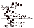
- The Fig. for #13 above shows a side view of the inclined
plane and the bar that carries a current out of the page.
The forces acting on the bar are the magnetic force Fm
to the left, the gravitational force mg, and
the normal force N.
- Fm = ILB. For the bar to remain at rest,
(Fnet)y = 0 and
(Fnet)x = mg sin 22.5o
- Fm cos 22.5o = 0 or
mg tan 22.5o = ILB.
I = mg tan 22.5o/LB = (1.2 kg)(9.8 m/s2)(0.414)/(2.0
m)(0.50 N/A-m)
= 4.87 A.
|
|
|
14.
|

I have taken up as north in Fig. for #14. In b of this figure,
you see that the compass points north. When the compass needle
is placed above a long current carrying wire (Fig. for #14c)
the needle points to the west. Point the thumb of your right
hand down. Above the wire your fingers and the magnetic field
lines are counterclockwise. The tangent to the field lines
is to the west, the direction of the magnetic field. The current
in the wire that produces this deflection of the compass needle
is south.
|
|
|
15.
|
The magnetic field lines
due to a current I into the page are clockwise. The tangent
to the magnetic field line at any point gives the direction
of the field at that point.
At P1, the magnetic field is down.
At P2, the magnetic field is to
the left.
|
 |
|
|
|
16.
|
The magnetic field B due to a very long
wire is directly proportional to the current I and inversely
proportional to the distance r from the wire.
- If I is doubled, B is doubled. If r is halved, B
is also doubled.
If I is doubled and r is halved, B goes up
by a factor of 4.
The new B is 4 x 0.50 T = 2.0 T.
- If I is halved, B is halved. If r is doubled, B
is halved.
If I is halved and r is doubled, B goes down
by a factor of 4.
The new B is 0.50 T/4 = 0.125 T.
|
|
|
17.
|
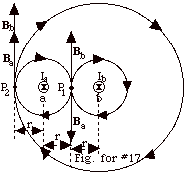
- The magnetic field lines for Ia (labeled a)
and the magnetic field lines for Ib (labeled
b) are shown in the Fig. for #17 above. Ia
= Ib = I. At P1, the magnetic
field due to Ia is Ba =
µoI/2pr
= Bb, the magnetic field due to Ib.
Bb = - Ba. The
resultant magnetic field at P1 is zero.
- At P2, the magnetic field Ba due
to Ia equals µoI/2pr,
and the magnetic field Bb due to Ib equals
µoI/2p
(3r), where r is the distance of P2 from Ia.
Both fields are up. The total field at P2
= µoI/2pr
+ µoI/6pr
= 2µoI/3pr
up.
- A proton out of the page at P2 experiences
a force to the left since v is out of the page and
B is up.
|
|
|
18.
|
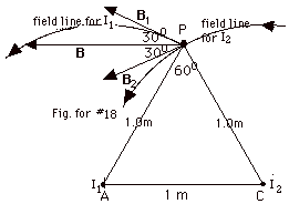
The magnetic field lines for very long current-carrying wires
are circles with the wire at the center. To find the direction
of the field line, point the thumb of your right hand in the
sense of the current and your fingers curl in the direction
of the field.
In the figure for both I1 and I2 the
direction of the field lines are counterclockwise. Notice
I have drawn both so they pass through P because that is where
I wish to find the field. The magnetic field at P is tangent
to the circle at P.
For I1, the circle has AP as a radius and
the field due to it B1 is perpendicular
to the radius and tangent to the field line so it is to the
left and up, as shown in the figure above.
Similarly, the radius for the field lines for I2
is CP, and B2 is perpendicular to CP and
tangent to its field line, so it is to the left and down.
The angle between B1 and B2
is 60o because B1 is perpendicular
to AP and B2 is perpendicular to CP. Two
angles that have their sides mutually perpendicular are equal.
Since I1 = I2 = 3 A and
r = 1.0 m, B1 = B2
= µoI/2pr
= 2 x 10⁻⁷ T-m/A (3A)/1m = 6 x 10⁻⁷
T.
B1y = B2y = B1 sin 30o,
but B1y is positive, while B2y is
negative so there is no component of B in the Y-direction.
B = 2B1x = 2B2x = 2B1 cos
30o = 2B2 cos 30o =
2(6 x 10⁻⁷ T)(0.866) =10.4 x 10⁻⁷ T
in the negative X-direction.
|
|
|
19.
|
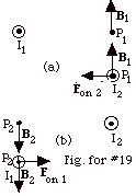
In Fig. for #19a above, I1 sets up a field
B1 at P1 up. A magnetic
field line with I1 at the center would be counterclockwise.
A tangent to this field line at P1 is up.
When I2 is placed at P1, it experiences
a force to the left.
In Fig. for #19b above, I2 sets up a field
B2 at P2 down. A magnetic
field line with I2 at the center would be counterclockwise.
A tangent to this field line at P2 is down. When
I1 is placed at P2, it experiences
a force to the right.
The field approach correctly predicts that two wires carrying
currents in the same direction attract each other.
|
|
|
20.
|
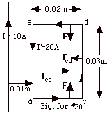
The magnetic field due to a very long wire is B = µoI/2pr.
For the long wire carrying a current I = 10 A at the position
of side ea
of the loop with r = 0.01 m = 10-2 m,
B = 2 x 10⁻⁷ N/A2(10A)/10-2
m = 2 x 10⁻⁴ N/A-m.
At the position of the side of the loop cd,
with r = 0.03 m = 3 x 10⁻² m,
B = 2 x 10⁻⁷N/A2(10A)/(3x10-2m)
= 2/3(10-4)N/A-m.
Along ed
and ac,
the field varies with the distance r from the wire, but is the
same for the same r.
To the right of the long wire, the magnetic field of the wire
is into the plane of the paper.
The force Fm on a wire carrying a current
I’ with length L in a magnetic field B is Fm
= I’(L x B), where the direction of
L is taken in the sense of I’ in that wire. For
all lengths of the wire,  L,
Bdue to the long wire is 90o
and sin 90o = 1. For the same value of r, B
at that position on the length de
or ac
is the same. The force on an element of length there is the
same magnitude, but opposite in direction because Lde
is to the left and Lac to the right. The net
force on Lde and Lac is zero. L,
Bdue to the long wire is 90o
and sin 90o = 1. For the same value of r, B
at that position on the length de
or ac
is the same. The force on an element of length there is the
same magnitude, but opposite in direction because Lde
is to the left and Lac to the right. The net
force on Lde and Lac is zero.
Fea = (20 A)(3 x 10⁻² m)(2 x 10⁻⁴
N/A-m) sin 90o = 12 x 10-5 N to the right.
Fcd = (20 A)(3 x 10⁻² m)(2/3 x 10-4
N/A-m) sin 90o = 4 x 10⁻⁵ N to the
left.
Net force on loop = (12 - 4) x 10-5 N = 8 x 10⁻⁵
N to the right.
|
|
|
21.
|
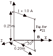
There will be equal forces up and down on the upper and lower
parts of the loop, respectively, but they will not produce
any torque about the Y-axis. The force on length cd with I
= 1.0 A, L = -0.25mj, and B = 0.5 N/A-m
i is
Fm = 1.0 A(-0.25 m j x 0.5 N/A-m
i) = 0.125 N k. The torque t
= (r x F), where r is drawn from the axis
to the point of application of the force F. The angle
between r and Fm is 60o.
The magnitude of r is 0.20 m and the magnitude of Fm
is 0.125 N. t
= (0.20 m)(0.125 N) sin 60o = 0.022 N-m. The
direction of the torque from t
= r x Fm is in the negative
y or - j direction.
|
|
|
22.
|
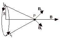
To find the direction of the field at P, point the thumb
of your right hand at the upper (u) portion of the loop, out
of the page. For this element, you can think of the magnetic
field lines as being a concentric circle about it. At
P, the tangent to the line would be in the direction of Bu.
Now go to an element at a lower portion of the loop. Again
point your thumb there in the sense of the current or into
the page. At P, the field due to this current at P is
shown as Bl. For every other element of
the loop, the magnetic field vectors will make a cone about
P. The components of the vectors in the Y and Z direction
cancel, leaving the direction of the field in the positive
X direction. When you look at a circular coil carrying a current
in a counterclockwise direction, the magnetic field is along
the axis of the coil, outward.
|
|
|
23.
|
If the velocity v is parallel
to the axis of the loop, it is parallel to the magnetic
field,  v,B
= 0, and the force on it is zero. The electron will continue
merrily on its path. v,B
= 0, and the force on it is zero. The electron will continue
merrily on its path.
|
|
|
24.
|

- For a very long solenoid, the magnetic field inside the
solenoid, far from either end, is a constant with Bsolenoid
= µonIsolenoid, where n is the
number of turns per unit length.
B = (4p x 10-7
N/A2)(1000/m)(0.20 A) = 2.5
x 10-4 N/A-m = 2.5 x 10⁻⁴ T.
When viewed from the right end of the solenoid, the current
is counterclockwise. The magnetic field points to the right,
as shown in the figure above.
- The magnetic field due to the very long wire Bwire
= µoIwire/2pr.
For a current in the wire to the left, below the axis of
the solenoid at P the magnetic field due to the current-carrying
wire is out of the page. The resultant field due to both
makes an angle of 45o when
Bsolenoid = Bwire or
µonIsolenoid = µoIwire/2pr
or
r = (Iwire/Isolenoid)/2pn
= (6.0/0.2)/(2000p
m-1)
= 4.8 x 10⁻³ m = 4.8 mm.
|
|
|
25.
|

In the figure above the dashed circles represents paths around
which you can evaluate Ampere's law. There is also
a path for a < r < b that is solid with arrows to denote
a magnetic field. Notice that  B,ds
= 0. B,ds
= 0.
From Ampere's law,  (current
enclosed) (current
enclosed)
By symmetry for all cases,  B,ds
= 0, and B is constant everywhere on the surface so, B,ds
= 0, and B is constant everywhere on the surface so, 
In general, B2pr
= µo (current enclosed)
- For r ≤ a, B2pr
= µo (0) = 0
- For a ≤ r ≤ b, the current
enclosed = NI, where N = the number of turns. B2pr
= µo NI and
B = µoNI/2pr.
- For r ≥ b, the current enclosed = I - I = 0 and
again B = 0.
|
|
|
26.
|
There are two problems concerning magnetic
fields, just as there were for electric fields.
- Given a distribution of current elements, find the magnetic
field due to these current elements. There are three approaches
to this problem:
- use the field due to a single long wire and then
find the field due to a number of them by vector addition;
- use the Biot-Savart law for unsymmetrical situations;
and
- use Ampere's Law for symmetrical situations.
- Given a magnetic field, find the force on
- a moving charged particle, Fm =
q(v x B)
for a positively charged particle and
- a current-carrying wire of length L, Fm
= I(L x B).
|
|
|
27.
|
- The force dF = (6 A)(dx)B sin 90o = (6 A)(dx
m)(1 + 3x2 m-2)N/A-m(1).
- Unit of dF is N. The direction of dF is in the
+Z-direction.
- dty =
x dF sin 90o = x(m) (6 A)(dx m)(1 + 3x2
m-2)N/A-m
= 6x(1 + 3x2
m-2)N-m.
- dtz = 0.
dF is parallel to the Z-axis.
- F =
 6N / m(1 + 3x2m-2)dx = 6(0.5 + 0.125)N = 3.75N. 6N / m(1 + 3x2m-2)dx = 6(0.5 + 0.125)N = 3.75N.
|
|
|
|
|
|
|
30.
|
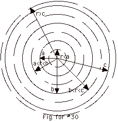
For r ≤ a, the current density = Jr≤a
= I/pa2
Current enclosed by circle of radius r = (l/pa2)pr2
= Ir2/a2.
For a ≤ r ≤ b, current enclosed
= I
For b ≤ r ≤ c, the current density =
Jb≤r≤c = - I/p(c2-b2)
Current enclosed = I[1 - p(r2
- b2)/p(c2
- b2)] = I[(c2 - r2)/(c2
- b2)].
For r ≥ c, current enclosed = I - I = 0.
Only the cross-sections of the coaxial cylinders are shown in
the figure above. The dashed circles in the figure are the paths
drawn to evaluate
 = µoI. = µoI.
By symmetry, B is tangent to the path and constant for a given
r.
For r ≤ a or a ≤ r ≤
b, the magnetic field lines are counterclockwise for the
current of the inner cylinder out of the page.  B,
d B,
d =
0. =
0.
Since B is constant over the path,  B (2pr). B (2pr).
This is true for all values of r.
- For r ≤ a, B2pr
= µo(current enclosed) = µo(Ir2/a2),
and
B
= µo(Ir/2pa2)
- For a ≤ r ≤ b,
B2pr = µoI and
B = µoI/2pr
- For b ≤ r ≤ c
B2pr = µoI[(c2
- r2)/(c2 - b2)]
B = µoI[(c2 -
r2)/(c2 - b2)]/2pr
- For r ≥ c B2pr
= 0 and B = 0.
|
|
|
31.
|
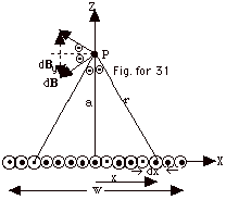
Number of wires/length = N/w. Number of wires in length
dx = (N/w)dx.
- For length dx, dB = NµoI dx/2prw
= NµoI dx/2pw(x2
+ a2)1/2.
- If you point the thumb of your right hand in the direction
of the current at x, the magnetic field line through point
P is counterclockwise. The tangent to the field line at
P is perpendicular to the radius r of the circle in the
direction of dB in the figure above.
For a corresponding dx on the left hand of the origin, the
dB would be perpendicular to the line from dx to P. You
can see from the figure that the components of the dB's
in the Y-direction dBy cancel. The resultant
component is in the negative X-direction.
dBx = dB cos Q =
Nµo(I/w) dx/2p(x2
+ a2)1/2 (a/(x2 +
a2)1/2)
= Nµo(I/w)a dx/2p(x2
+ a2).
Let x = a tan Q.
dx = a sec2QdQ.
dBx = Nµo(I/w)a2
sec2 QdQ/2p(a2
tan2 Q
+ a2)
= Nµo(I/w)a2
sec2 QdQ/2pa2sec2
Q
= (NµoI/2wp)
dQ.
The lower limit on x is - w/2 and the upper limit on
x is + w/2.
The lower limit on Q
is tan -1 (-w/2)/a and the upper limit
on Q
is tan-1 (+ w/2)/a.
B = (NµoI/2p)
d Q (NµoI/2p)
d Q
= (NµoI/2wp)[tan-1
(+w/2)/a - tan-1 (-w/2)/a]
= (NµoI/wp)[tan-1
w/2a].
|
|
|
32.
|
- The magnetic moment µ = IpR2.
- B = µoIpR2/2p(R2
+ z2)3/2 becomes
B = µoµ/2p(R2
+ z2)3/2.
- For z >> R, you can neglect R in the denominator
of B and then you have 2p(z2)3/2
= 2pz3 and
B becomes
m o m/2pz3.
- B = 2 x 10⁻⁷ N/A2 (9.27 x 10⁻²⁴
A-m2)/(10-10 m)3 = 1.9
N/A-m = 1.9 T.
- The spinning electron gives a field and magnetic moment
opposite in direction to a positive charge moving in a loop.
Since both change sign, the net effect for the potential
energy will be the same as for current loops. That is U
= - m . B
= - µB cos
 m,B. m,B.
- When they are aligned they will have minimum energy.
- Antialigned U = µB
=
9.27 x 10⁻²⁴ A-m2 x 1.9 N/A-m/(1.6
x 10-19 J/eV)
=
1.1 x 10⁻⁴ eV.
|
|
|