|
Outline - Physical Optics
|
|
- Descriptive Terms of Wave Motion
- Amplitude is the maximum displacement from the equilibrium
position.
- Velocity is the distance moved by the wave in one second.
The velocity of a wave depends on the medium in which the
wave travels.
- Wavelength λ is the
distance moved by the wave in one complete oscillation of
the source. The distance between crests is one wavelength.
The wavelength depends on the medium in which the wave travels.
- Frequency f is the number of oscillations of the source
per second. Frequency depends on source and does not change
when wave goes into a different medium.
- Period T is the time for one complete oscillation. The
period depends on the source and does not change when the
wave enters a different medium.
- Velocity v is the distance moved by the wave in one second.
- (distance moved/oscillation)(#of oscillation/s) = (distance/s)
( λ)(f) = v
- Light in a medium
- The index of refraction n of a medium is defined as the
ratio of the speed of light in a vacuum (or air) c to the
speed of light in a medium v.
n = c/v
- In a vacuum (or air), for light of frequency f, wavelength
λo,
and velocity c,
λof
= c
(Equation
1)
- In a medium of index of refraction n, for light of frequency
f,
wavelength λn,
and velocity v,
λnf
= v
(Equation
2)
Dividing Eq. 1 by Eq. 2,
λo/ λn
= c/v = n or
λn= λo/n.
Wavelength is directly proportional to velocity. When the
velocity of a wave in a medium decreases the wavelength decreases.
- Interference
- Constructive and Destructive interference
- Constructive interference occurs when a crest falls
on a crest and a trough falls on a trough. Destructive
interference occurs when a crest falls on a trough.
- For constructive interference, the path difference must
equal an integral number of wavelengths. For destructive
interference, the path difference must equal half-integral
number of wavelengths.
- In Fig. 1 below, the wave from source 1 has traveled
a distance S1P to point P and the wave from
source 2 has traveled a distance S2P to point
P. The path difference = S1P - S2P.
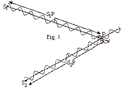
- For constructive interference, S1P - S2P
= m λ, m = 0, 1, 2,
etc.
- For destructive interference, S1P - S2P
= (m + 1/2) λ.
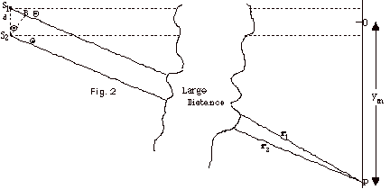
- Fig. 2 below shows two point sources, S1 and
S2, emitting waves that are detected at a distant
point P from the two sources. The distances r1
and r2 from sources 1 and 2 to the point P are
large compared to the separation d of the sources. For this
case, the two rays along the lines of sight from the two sources
to point P are nearly parallel, both being essentially at
the same angle Θ from
the X axis as shown in the figure. Since I am unable to draw
such large distances and at the same time show the path difference,
S1P - S2P = S1B, as a reasonable
length, I have made a “break” in the drawing as
the two "parallel" rays come together and arrive
at P.
- If point P is one of maximum intensity (constructive
interference),
S1B = m λ.
If point P is one of minimum intensity (destructive interference),
S1B = (m + 1/2) λ.
- From triangle BS1S2, we see that
sin Θ = S1B/d
or
d sin Θ = S1B.
- For constructive interference, d sin Θ =
m λ.
- For destructive interference, d sin Θ =
(m + 1/2) λ.
- In Fig. 3 below, ym represents the distance on
the screen from center of the intensity pattern to a position
of constructive or destructive interference and L the distance
from the slits to the screen.
sin Θ = ym
/(L + ym2)1/2

- For ym << L, sin Θ
is approximately = ym/L = tan Θ
- When ym << L
- For constructive interference,
- sin Θ =
m λ/d = ym/L
or
ym = m λL/d
- ym + 1 – ym = [(m
+ 1) – m] λL/d
= λL/d =
distance between maxima.
- For destructive interference,
- sin Θ =
(m + 1/2) λ/d
= ym/L or
ym = (m + 1/2) λL/d
- ym + 1 – ym = [(m
+ 1 + 1/2) – (m + 1/2)] λL/d
= λL/d = distance
between minima.
- Sample Problems: 108
Problem Set for Physical Optics, 1-5, 12, 15,
16, and 17.
- Phase Change at Interface
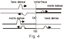
- When a pulse goes from a less to a denser medium, the reflected
wave experiences an 180o or π
phase change. When it goes from a more to a less dense medium,
there is no change of phase for the reflected wave. (Fig.
4 above).
From a crest to a trough is a distance of λ/2.
A change of phase of 180o or π is
equivalent to a path difference of λ/2.
Notice that there is never a change of phase for the transmitted
ray at an interface. The speed of light is greatest in a vacuum
or approximately air with index of refraction n = 1 = c/v.
The higher the index of refraction, the smaller the speed
of the wave.
When light goes from medium 1 to medium 2, the reflected ray
will experience a phase change of π if
n2 > n1. There will be
no phase change if n2 < n1.
- Boundary Conditions Applied to Waves

- In Fig. 5a above, the incident wave I is reflected at
the first interface of a less dense-more dense medium,
where the index of refraction in the incident medium n1
< n, the index of refraction in the film. There
is an 180o or π change
in phase at the first interface. There is no change in
phase for the transmitted wave T. And there is no change
in phase at the second interface of a more dense-less
dense medium with n3 < n.
The "real" path difference for 5a or 5b above
is 2t, where t is the thickness of the medium. A change
of phase of π for
the incident ray is equivalent to an additional path difference
of λn/2,
where λn
is the wavelength in the film. For Fig. 5, the index of
refraction of the film is n. Remember that the wavelength
in a medium λn
= λ/n where λ
is the wavelength in a vacuum.
The condition for
- maximum:
2d = (m +1/2) λn
or
2d = (m +1/2) λ/n
or
2nd = (m +1/2) λ
- minimum:
2nd = m λ
- Because of the change in phase of π,
the conditions for maxima and minima have been reversed.
- In Fig. 5b, the incident wave I is reflected at the
first interface of a less dense-more dense medium
where the index of refraction in the incident medium n1
< n, the index of refraction in the film. There
is an 180o or π change
in phase at the first interface. There is no change in
phase for the transmitted wave T. There is another change
of phase of π at the
second interface since n3 > n.
The total phase change is 360o or 2 π. That is equivalent to no phase change
overall.
The condition for
- maximum:
2nd = m λ
- minimum:
2nd = (m + 1/2) λ
- Sample Problems: 108
Problem Set for Physical Optics, 13,
14, 19 and 20.
- Interference for Multiple Slits
- For multiple slits with equal spacing d, the condition for
maxima is identical to that for 2 slits with a separation
of d: sin Θ =
m λ/d
- Rather than giving the spacing d, you usually get the number
of slits per length. The reciprocal of the number of slits
per length is equivalent to d, but be careful that the length
is in meters.
- Sample Problems: 108
Problem Set for Physical Optics, 12,
16, and 26.
- Diffraction (Intensity pattern shown in Fig. 8 below)
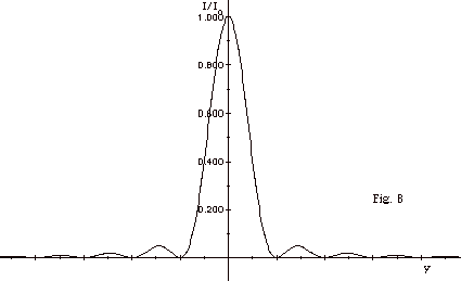
- Diffraction is really interference from a very large number
of sources and slits.
- Think of a single slit as made up of an infinite number
of sources and slits. In Fig. 7 below, I have only divided
it up into a few sources.
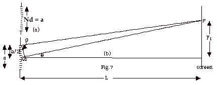
- In Fig. 7a, with N the number of slits and d the distance
between each slit, the slit width a = Nd.
- Conditions for a Maximum
- Since the condition for a maximum is the same for N
slits with a separation d as it is for 2 slits with a
separation d, you get a maximum when sin Θ=
m λ/d = Nm λ/a.
- Since N is a very large number, sin Θ will
be greater than 1 unless m = 0. There is only
one principal maximum and that occurs at the center of
the screen.
- Conditions for a Minimum in a Diffraction Pattern
- The width of the slit is a. Think of light coming from
an element of length dy at the top of the slit and an
element of length dy half way down on the slit as shown
in Fig. 7b above. Obviously there is a path difference
between them when the light from the top and middle of
the slit arrive at P.
- Destructive interference occurs if this path difference
for the element at the top of the slit and the element
at the center of the slit is λ/2.
This will also be true for other elements that you
pair as you go down the slit with path differences
of λ/2.
- In the little triangle on the left, for destructive
interference, sin Θ = ( λ/2)/(a/2)
= λ/a, the condition
for the first minimum.
- For the second minimum, divide the slit into four parts
and match elements that give a path difference of λ/2.
The second minimum occurs for sin Θ
= ( λ/2)/(a/4) = 2 λ/a.
- Continuing in this way, you find for the mth minimum:
sin Θ
= m λ/a
- Position of Minima on Screen
- From Fig. 7 above, tan Θ=
y/L. For small Θ,
tan Θ ≈
sin Θ.
- From VI, E, 3 above, sin Θ
= m λ/a.
For sin Θ ≈
tan Θ, m λ/a
= ym/L, or
ym = m λL/a,
where ym corresponds to the mth mimimum.
- The distance between minima =
Δy = ym+1
- ym = (m + 1) λL/a
- m λL/a = λL/a.
- Since the width of the central maximum = the distance
between the first minimum on the right and the first minimum
on the left of the central maximum, the width of the central
maximum = 2 λL/a.
- Sample Problems: 108
Problem Set for Physical Optics, 21,
22, and 24.
- Diffraction Limit
- Diffraction poses a fundamental limit on the ability of
optical systems to distinguish closely spaced objects.
- Assume light from two point sources far from a slit
illuminates the slit. Light diffracting at the slit produces
two single-slit diffraction patterns, one for each source
as shown in Fig. 9 below.
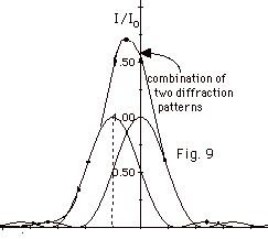
- Because the sources are at different angular positions,
the central maxima of the diffraction patterns overlap.
- The result in Fig. 9 is one big blob and you can't distinguish
two separate objects.
- Rayleigh's Criterion
- If the angular separation of the two objects is great
enough, you see a separation of the two maxima and can
distinguish the existence of two objects.
- The two peaks are barely distinguishable if the central
maximum of one coincides with the first minimum of the
other. We found earlier that sin Θ = λ/a for the first minimum in single-slit diffraction.
The angular separation between the diffraction peaks equals
the angular separation between the sources. In most optical
systems, the wavelength of the light is much smaller than
the aperture. In the small angle approximation, sin Θ is
approximately equal to Θ,
the Rayleigh condition that the two sources be just resolvable
gives for a slit
Θmin
= λ/a
- The Rayleigh criterion for circular apertures is
Θmin
= 1.22 λ/D,
where D is the aperture diameter.
- Sample Problem: 108
Problem Set for Physical Optics, 25.
- Polarization
- Polarization is the attribute that a wave's oscillation
have a definite direction relative to the direction of propagation
of the wave.
- The direction of the polarization is parallel to the
electric field of the electromagnetic wave and perpendicular
to the direction of the propagation of the wave.
- Light waves are transverse waves that may be polarized.
- Natural light is partially polarized. This means that the
electric field vectors associated with this light are not
in one direction.
- The electric field vectors can be resolved into two
vectors perpendicular to each other.
- When you send light through a polaroid, the electric
field vector perpendicular to the transmission axis is
absorbed, leaving only the component along the transmission
axis of the polaroid.
- When unpolarized light with intensity of the incident
light equal
to Ii is sent through a polaroid, the intensity
of the light is reduced by a factor of 2. The transmitted
intensity It = Ii/2.
- Polarized Light passing through a polaroid
- Figure 13a below represents polarized light with incident
electric field Ei approaching a polaroid. The
direction of the transmission axis is indicated with a
dash line. The transmitted electric field Et
is smaller and rotated through an angle Θ
along the transmission axis.
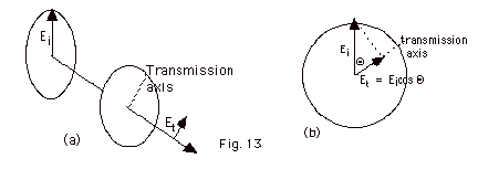
- Figure 13b above gives an end view. The component of
E1 along the transmission axis is the transmitted
electric field Et = Ei cos Θ.
- The Poynting Vector = the intensity of the light I =
Emax2/2µoc.
The intensity is proportional to the electric field, that
is,
I = kE2, where k is a constant.
- The initial intensity Ii = kEi2
- The transmitted intensity It = kEt2
= kEi2 cos2 Θ
- It/ Ii = cos2
Θ
- Polarization by Reflection
- The incident ray in Fig. 15 below is unpolarized. It
has components of the electric field perpendicular to
the plane of the paper represented by a dot • and
a parallel component in the plane of the paper represented
by an arrow
 . .
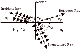
- When the angle between the reflected ray and the transmitted
ray is 90o, the reflected ray cannot contain
any of the parallel component because then the electric
field would be in the direction of the propagation and
that is not possible. The transmitted ray has parallel
components of the electric field and some perpendicular
components of the electric field.
- When the reflected ray has only components of the electric
field perpendicular to the paper, the reflected light
is plane polarized. The angle of incidence when you get
plane polarized light in the reflected ray is called the
Brewster angle ΘB.
- Snell's law states that ni sin Θi
= nt sin Θt.
- For Θi
= ΘB,
Θr
+ Θt
= 90o.
- Since Θi
= Θr,
and for this case Θi
= ΘB,
ΘB +
Θt
= 90o or
Θt
= 90o - ΘB
- Snell's law becomes ni sin ΘB
= nt sin (90o - ΘB)
= nt cos ΘB
or
tan ΘB
= nt/ni.
- If the light is incident from air with nI =
1,
tan ΘB
= nt.
- Sample Problems: 108
Problem Set for Physical Optics, 28 -
31.
- Addition of Wave Amplitudes Using Phasors
- Imagine we have two waves with different amplitudes. We
can write the equations of the waves
y1(r1,t) = A1 cos
(ωt - kr1)
and
y2(r2,t) = A1 cos (ωt
- kr2),
where ω = 2 πf
and f the frequency of the waves, and
where k = 2 π/ λ
and λ the wavelength of
the waves.
We can represent them as the horizontal components of a vector
that rotates counterclockwise with angular speed ω.
The length of the vector represents the amplitude of the wave
and the angle between them represents the phase difference ΔΦ,
as illustrated in Fig. 16 below.
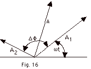
The phase angle is defined as (2 π/ λ)(r2
- r1), where (r2 - r1) is the
path difference. The resultant amplitude is the horizontal component
of the vector sum.
- If ΔΦ = 2m π
for m = 0, 1, 2, . . .
as in Fig. 17 a below, the interference is constructive.
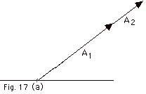
For ΔΦ = 2m π,
the path difference (r2 - r1) = m λ
as we found before.
- If ΔΦ = 2 π
(m +1/2) for m = 0, 1, 2, . . .
as in Fig. 17 b below, the interference is destructive.
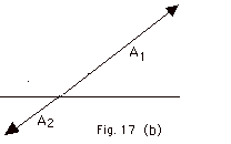
For ΔΦ = 2m π,
the path difference (r2 - r1) = (m
+ 1/2) λ as we found
before.
- Using non-rotating phasor diagrams for determining maximum
amplitude at a point
Example:
Two radio transmitters both of the same initial phase and amplitude
have a wavelength of 30 m. A distance of 25 m separates the
transmitters. We wish to find the resultant amplitude of these
two radio transmitters in the directions (a), (b) and (c) shown
in Fig. 18 below.
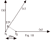
- For direction (a) the path difference is 25 m and
ΔΦ= (2 π/ λ)(r2
- r1) = (2 π/30
m)(25 m) = 5 π/3 = 300o.
The phasor diagram for this direction is shown in Fig. 19a
below.
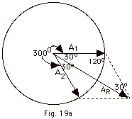
Since the amplitude of both transmitters is the same, we
draw a circle for the phasor diagram. We arbitrarily draw
A1 to the right on what would be the X-axis and
A2 rotated counterclockwise at an angle of 300o.
We draw the diagonal of the parallelogram to find the resultant
amplitude AR. By geometric considerations, we
see the small angles of the triangle are 30o,
leaving the angle opposite the resultant amplitude as 120o.
Letting A1 = A2 = A and using
the law of cosines,
AR2 = A2 + A2 -
2A2 cos 120o = 3A2.
Since the intensity of a wave is proportional to the square
of the amplitude, the resultant intensity is three times
the intensity of either source.
- For direction (b) the path difference equals zero (the
parallel rays meet at a very far distance away). The resultant
amplitude is 2A and the resultant intensity is proportional
to 4A2.
The phasor diagram for this direction is shown in Fig. 19b
below.
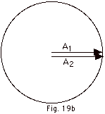
The intensity is four times the intensity due to one source.
- For direction (c) the path difference = the length S1B
in Fig. 18.
This path difference = 25 m sin 37o = 15 m.
ΔΦ= (2 π/ λ)(r2
- r1) = (2 π/30
m)(15 m) = π = 180o.
The phasor diagram for this direction is shown in Fig. 19c
below.
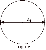
The resultant intensity is zero.
- Sample Problems: 108
Problem Set for Physical Optics, 6, 7,
and 9.
|
|