| Outline - Geometric Optics |
Note
that I have used:
so
= object distance, si = image distance,
Θi
for the incident ray, Θr
for the reflected ray,
Θt
for the transmitted ray. |
|
|
- Descriptive Terms for Wave Motion
- Velocity is the distance moved by the wave in one second.
The velocity of a wave depends on the medium in which the
wave travels.
- Wavelength λ is the
distance moved by the wave in one complete oscillation of
the source. The wavelength depends on the medium in which
the wave travels.
- Frequency f is the number of oscillations of the source
per second. Frequency depends on source and does not change
when wave goes into a different medium.
- Period T is the time for one complete oscillation. The period
depends on the source and does not change when the wave enters
a different medium.
- Velocity v is the distance moved by the wave in one second.
- (distance moved/oscillation)(#of oscillation/s)=(distance/s)
( λ)(f) = v
- Light in a medium
- The index of refraction n of a medium is defined as the
ratio of the speed of light in a vacuum (or air) c to the
speed of light in a medium v.
n = c/v
- In a vacuum (or air), for light of frequency f, wavelength
λo,
and velocity c,
λof
= c (Equation
1)
- In a medium of index of refraction n, for light of
frequency f,
wavelength λn,
and velocity v,
λnf
= v (Equation
2)
Dividing Eq. 1 by Eq. 2,
λo/ λn
= c/v = n or
λn= λo/n.
Wavelength is directly proportional to velocity. When the
velocity of a wave in a medium decreases the wavelength decreases.
- Descriptive Terms for Ray Diagrams
- The Descriptive Terms
- Angle of incidence Θi
is the angle between the incident ray and the normal to
the surface.
- Angle of reflection Θr
is the angle between the incident ray and the normal to
the surface.
- Angle of refraction or transmission Θt
is the angle between the refracted (transmitted) ray and
the normal to the surface.
- From Snell's law,
ni sin Θi
= nt sin Θt
sin Θt =
ni sin Θi
/ nt
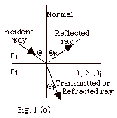
- If the transmitted medium is more dense than the incident
medium
(nt > ni),
sin Θt
< sin Θi,
Θt <
Θi,
and the light is bent toward the normal. See Fig.
1a below.
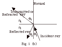
- If the transmitted medium is less dense than the incident
medium
(nt < ni),
sin Θt
> sin Θi,
Θt > Θi,
and the light is bent away from the normal. See
Fig. 1b below.
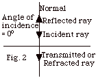
- When an incident ray hits a surface normally, the angle
between the incident ray and the normal is 0o
and, by definition, the angle of incidence is 0o.
For an angle of incidence of 0o, the angle
of reflection is 0o, and the angle of refraction
is 0o regardless of the relative values of
ni and nt, as shown in Fig. 2 below.
- Sample problems in the 108
Geometric Optics Problem Set: 1-3, 5, 6, 9,
11.
- Total Internal Reflection
- Occurs only when light goes from a denser medium
to a less dense medium, that is, ni is greater
than nt. In Fig. 3 below, the smallest
angle of incidence from the more dense material is shown with
one arrow. The corresponding refracted ray is also shown with
one arrow. As you increase the angle of incidence (ray with
two arrows), the angle of refraction increases.
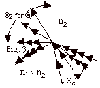
- When you hit the critical angle Θc
(ray with three arrows), the refracted ray skims along the
interface between the two media.
For an incident angle = Θc,
the angle of refraction Θt
= 90o.
In general, ni sin Θi
= nt sin = Θt.
For Θi = Θc,
n1 sin Θc
= nt sin 90o or
sin Θc = nt/ni.
For any angle greater than Θc,
the light is totally internally reflected as shown by
the ray with four arrows in Fig. 3 above.
- Sample problems in the 108
Geometric Optics Problem Set: 7, 8, 12.
- Locating Images
- You need two rays to find the location of an image.
- For a real image, the two rays actually meet at a point.
- For a virtual image, you trace the two rays back until
you find the point at which they appear to meet.
- Image for a plane mirror

- In Fig. 4a, a ray from the top of the object O hits
the mirror normally. The angle of incidence is 0o
and the angle of reflection is 0o. The
incident and reflected ray are shown with one arrow.
- In Fig. 4b, an incident ray at angle Θi
and a reflected wave ray at angle Θr
are shown with two arrows.
- In Fig. 4c, only the two reflected rays are shown.
The eye "thinks" light travels in straight lines.
It traces the two rays back and finds they appear to meet
at the location of the top of the image I. The foot of
the object, which rests on the normal to the surface,
is automatically positioned below the top of the arrow.
- For a plane mirror, the image is as far behind the
mirror as the image is in front of the mirror. The object
distance so = the image distance si.
See solution to Problem 4 in 108
Solution Set for Geometric Optics.
- Apparent depth of an object in a medium
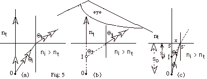
- In Fig. 5a, two rays are shown leaving the object O.
The ray with one arrow hits the surface normally and continues
into the other medium with no refraction. The ray at incident
angle Θi
in the medium of index of refraction ni>
nt is refracted at angle Θt
in the medium of index of refraction nt.
- In Fig. 5b, the eye is shown tracing the rays back to
the image I.
- In Fig. 5c , the angle of incidence for the second ray
is drawn small so the approximation of sin Θ
≈ tan Θ can
be used.
From Fig. 5c, we see tan Θt
= x/so and tan Θ1
= x/si.
From Snell's law, ni sin Θi
= nt sin Θt.
For our approximation, ni x/so =
nt x/si or
si = nt so /ni.
For nt = 1, si = so
/ni.
- Sample problems in the 108
Geometric Optics Problem Set: 4, 10.
- Mirrors
- For all mirrors, the relationship between the object distance
so, the image distance si, and
the focal length f is
1/ so + 1/ si = 1/f.
When solving this equation, remember to find the reciprocal.
For example, if you solve for 1/si by subtracting
1/so from 1/f, you must then take the reciprocal
to find si. The magnification m = - si/
so. If m is negative, the image is inverted.
For all mirrors, we take f = R/2, where R is the radius of
curvature of the mirror. Draw rays to and from a straight
line, but indicate what type of mirror you are using.
- Concave Mirrors
- Focal length is positive. The center of curvature is
in front of the mirror.
- For object distance so > f, image
is real and inverted.
- For so > 2f, image is diminished
in size.
2f < so < f, image is enlarged.
In Fig. 6a below, ray 1 (one arrow) goes through the focal
point F and is reflected back parallel to the principal
axis. Ray 2 goes through the center of Curvature C, hits
the mirror normally and is reflected back along it. Ray
3 is parallel to the principal axis and reflected back
through the focal point. These three rays meet at the
top of the image at I’. The foot of the object O
rests on the principal axis and its image I also rests
there in a line with the top of the image. Image is real,
inverted, diminished in size.
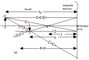
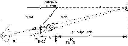
- For so < f, image is virtual, erect,
and magnified. The same incident rays used in Fig. 6a
above are used in Fig. 6b below. The eye traces back the
reflected rays, which appear to meet at the top of the
image at I’.
- Convex Mirrors
- Focal length for convex mirror is negative. The center
of curvature is at the back of the mirror.
- Images of a convex mirror are always virtual, erect,
and diminished in size.
- In Fig. 7 below, Incident Ray 1 (one arrow) is drawn
to the focal point F behind the mirror. It is reflected
back parallel to the principal axis. Incident Ray 2 is
drawn to the center of curvature C behind the mirror and
reflected back on itself. Incident Ray 3 is drawn parallel
to the principal axis and is reflected back as though
it had come from the focal point F behind the mirror.
The eye traces the rays back to find the head of the image
I’ back of the mirror.
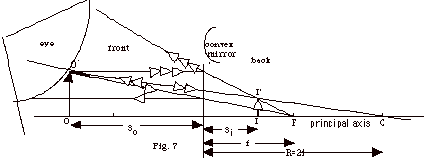
- For Fig. 7, let f = -3.4 cm and so
= 5.1 cm.
1/ si = 1/f – 1/so.
1/si = -1/3.4 cm – 1/5.1 cm = 0.490 cm-1.
si = -2.0 cm.
The negative value of si indicates that it
is a virtual image.
The magnification is m = - si/so
= - (-2.0 cm)/5.1 cm = +0.39.
The image is erect and diminished in size.
- Sample problems in the 108
Geometric Optics Problem Set: 21, 22.
- Lenses
- For all lenses, the relationship between the object distance
so, the image distance si, and
the focal length f is
1/so + 1/si = 1/f.
The magnification m = - si/so. Draw
refracted rays from line through the center of the lens, indicating
whether the lens is converging or diverging.
- Converging Lens
- Focal length is positive.
- For so > f, the image is real and
inverted.
- For so > 2f, the image is diminished
in size.
For so = 2f, m = 1.
- For 2f > so > f, the image is
enlarged.
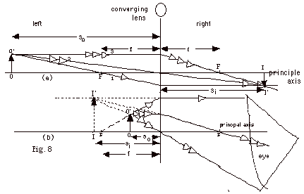
- In Fig. 8a below, Ray 1 (one arrow) is drawn through
the focal point F and is refracted parallel to the principle
axis on the left. Ray 2 is drawn through the center of
the lens and passes through it without being refracted.
Ray 3 is drawn parallel to the principal axis and is refracted
through the focal point F on the right. The three rays
from the top of the object meet at the top of the image
I’. The foot of the image I is on the principal
axis. The image is real, inverted, and diminished in size.
- For so < f, the image is virtual,
erect, and magnified.
In Fig. 8b above, the same three rays are drawn, but these
rays diverge on the left side. The eye traces the rays
and “sees” them as though the top of the image
was at I’. For a converging lens and virtual image,
the image distance is negative but greater than
the object distance. The image forms behind the
object.
- Diverging Lens
- The focal length is negative. For all object distances,
the image is virtual, erect and diminished in size. The
image distance is negative and less than the object
distance. The image forms in front of the object.
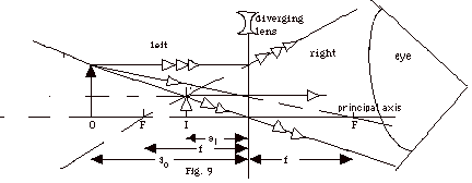
- In Fig. 9 above ray 1 is drawn so that it would go through
the focal point on the right side of the lens. It is diverged
so that it comes out parallel to the principal axis. Ray
2 continues through the center of the lens. Ray 3 is parallel
to the principal axis and diverges as though it had come
from the focal point to the left of the lens. For all
values of so, the rays diverge as they pass
through the lens and do not form an image on the right.
To the eye these refracted rays appear to come from the
top of the image at I’.
- Eye Defects and Corrections
It is customary to speak about the dioptric power D
of a lens, which is the reciprocal of the focal length. You
must first give the focal length of the lens in meters and
then take the reciprocal of this. 1 m-1 =
1 D.
- Nearsightedness
- Light rays originating from a long distance away
(so = infinity), focus behind the retina.
The largest distance the person can see is at her
far point. For the contact lens or glasses that correct
nearsightedness the image distance si
= - far point and the object distance = so
= ∞. With this correction, she will see
the object at infinity as though it had come from
her far point.
Since 1/f = 1/so + 1/si = 1/∞
- 1/far point = 0 - 1/far point
= -1/far point and
f = - far point.
To correct nearsightedness, you must use a diverging
lens.
- Notice the image distance at the far point is smaller
than the object distance at infinity so we could have
guessed she needed a diverging lens.
- Farsightedness
- The ideal nearness of an object that can be seen
by the eye is taken to be 25.4 cm. A person who is
farsighted needs to have the object further away than
25.4 cm. The distance for which a farsighted person
can see comfortably is called her near point. In correcting
for farsightedness, si = - near point.
The image distance is negative because it is a virtual
image and so = 25.4 cm. Now 1/f
= 1/so + 1/si = 1/25.4 cm -
1/near point.
Since the near point distance is greater than 25.4
cm,
1/near point < 1/25.4 cm and
f > 0, so that the corrective lens will be
a converging lens.
- Notice the image distance is greater than
the object distance so you would expect to use a converging
lens.
Caution:
Remember to express the dioptric power in m-1.
- Sample problems in the 108
Geometric Optics Problem Set: 13-15, 17, 18,
24, 26, 27.
- Optical Instruments
- Magnifying glass
- A magnifying glass uses a converging lens.
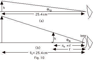
- Magnification is defined as Θa/Θu,
where Θu
is the angle the unaided eye makes with the object of
height h (Fig. 10a above), and Θa
is the angle the eye makes with the object of height h
when assisted by a lens (Fig. 10b above). The lens allows
you to move the object closer to the eye than 25.4 cm.
From Fig. 10a, you see so is approximately
equal to the focal length f of the lens. Also from Fig.
10a, we find tan Θu
= h/25.4 cm and tan Θa =
h/f. For small angles, the angle in radians is approximately
equal to the tangent of the angle.
m = Θa/Θu
≈ tan Θa/Θu
= (h/f)/(h/25.4 cm) = 25.4 cm/f = magnification of magnifying
glass.
- Microscope
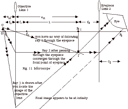
- A microscope consists of two lenses. The one closest
to your eye (lens 2 in Fig. 11) is called the eyepiece
and the other lens is called the objective (lens 1 in
Fig. 11). In Fig. 11, you locate the image of the objective
with ray 1 through the center of the lens and ray 2 through
the focal point of lens 1 which refracts parallel to the
principal axis. When ray 2 goes through the eyepiece,
it is refracted through the focal point of the eyepiece.
You can then draw ray 3 because every ray that comes from
the top of the object must arrive at the top of the image.
You draw ray 3 so it will pass through the center of the
eyepiece.
- Light enters through the objective. You want the image
of the objective
- to be a real image, and
- to be formed at the focal point of the eyepiece.
- The image of the objective becomes the object for
the eyepiece. Since the object of the eyepiece is
at its focal point, the image of the eyepiece will
be at infinity. These rays are the most restful on
your eyes because your eye is set for this distance
and does not need accommodation.
- The image of the objective is found from 1/fo
= 1/so1 + 1/si1, where
fo is the focal length for the objective
lens.
- Magnification
- The magnification of the objective mo
= - si1/so1
- Another formula for mo can be found
in the following way taking the "length"
L of the tube as si1 – fo.
First solve for si1 from 1/fo
= 1/so1 + 1/si1.
1/so1 = 1/fo -1/si1
= (si1 - fo)/ si1fo
or
so1
= si1fo /(si1
- fo) .
Then mo = - si1/so1
= - si1(si1 - fo)/si1fo
= - L/fo.
- The magnification of the eyepiece is the magnification
of the magnifying glass.
mE = 24.5 cm/fE
- Total M = mo mE = - si1/so1(24.5
cm/fE) = - L/fo(24.5 cm/fE).
- Telescope
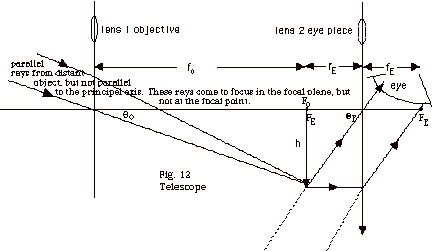
- Parallel rays from a distant object, but not parallel
to the principal axis, are brought to focus in the focal
plane. Note top of image of height h in Fig. 12 above
is in the focal plane but not at the focal point.
- This image is formed at the focal distance fE
of the eyepiece. I have not shown the origin of the two
rays that go from the top of the image through the center
of the eyepiece and another parallel to the principal
axis of the eyepiece emerging through the focal point
of the eyepiece. The final image is at infinity.
- The magnification of a telescope is defined as the
ratio of angle ΘE
to Θo,
as shown in Fig. 12. For small angles the ratio
of these angles equals the ratio of their tangents. From
Fig. 12, we see that
m = tan ΘE/tan
Θo =
(h/fE)/ (h/fo) = fo/fE.
- Sample problems in the 108
Geometric Optics Problem Set: 16, 19, 20.
|
|